

This site uses non-intrusive cookies to enable us to provide a better user experience for our visitors. No personal information is collected or stored from these cookies. The Society's policy is fully explained here. By continuing to use this site you are agreeing to the use of cookies.
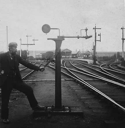
Plate 2/1 The ground post of the Manson system of tablet exchange apparatus at Forres South. By
pulling on the lever mounted at the side of the lineside post, the slider is moved into position nearer
the passing locomotive. (Author's collection)
James Manson, at the time Locomotive Superintendent of Great North of Scotland Railway, had experimented unsuccessfully with a means of avoiding hand exchanges by a device resembling that used in the exchange of mail bags. Only after discussions with John Duncan, a blacksmith with experience of cotton weaving machinery was the apparatus for exchanging tablets accorded the former's name successfully developed. This was introduced on the Coast Line and Fraserburgh branch of the GNSR in May 1889. It was then extended to the main line (only to be removed when doubled) to Keith, the Craigellachie route to Elgin, Speyside and Deeside branch lines. This was soon to be followed by its adoption on the Highland Railway.
To some extent the apparatus consists of two very similar parts of a collecting fork to receive the tablet and a spring clip deliverer to deposit the tablet. On the ground a cast iron pillar was bolted down onto a precast concrete base buried in the cess in a suitable position adjacent to the track, usually on the left hand side of both up and down loop lines. On the original Manson version, a horizontal sliding head moving normal to the track and operated by a lever was placed on the top of the standard, which when withdrawn and with the detachable head removed was clear of the structure gauge.
The ground apparatus on the Callander & Oban line, supplied by Tyer & Co, on the other hand was slightly different, in that a horizontal swinging arm replaced the slider, as an alternative means of moving the mount for the detachable head clear of the line, when not in use. Both of course required the intervention of man, rather than being automatically restored by the passing train.
Prior to the arrival of a train, a detachable head would be placed in a slightly tapered vertical slot on the outer end of the slider nearest the track. The head had a cross arm upon which was a fork facing the traffic to catch a pouch, containing the token, and a spring clip on the trailing end, but at a higher level to deliver another pouch to be collected. The receiving portion of the head was cast in brass or gunmetal in the shape of a fork between which were a pair of jaws hinged at the inner closed end of the fork. The pair of jaws was pressed together by rubber buffers acting against the inner surfaces of the fork. As the exchange was made, this assembly received and retained a leather pouch containing the token. On the trackside head, fixed by a bent arm to and above this metal fork, was a light parallel spring steel fork, with the open end facing away from the direction of traffic, in which a pouch would be placed to be collected by the engine as it passed. When not in use the entire detachable head was supposed to be kept in a cupboard close by, but if in frequent use they may have been left on the slider.
The engine apparatus was usually fixed on the left hand side of the cab of the engine with the collecting fork facing forward. The head on the engine was similar, but with the position of the spring catcher and delivery apparatus at the same level. On GNSR engines a detachable wrought iron spindle was fitted to a slider mounted transversely on the rear of the vertical face of the driving wheel splasher within the cab. With the head removed and stored within the engine and the slider withdrawn, it can be difficult to determine whether an engine is so fitted, or not. On the other hand, Highland and other companies' engines were provided with a hinged arm bolted to the exterior of the cab side. This folded back vertically against the cab-side when not in use, but a lever inside the cab could be raised to rotate the arm downwards into the horizontal position prior to making an exchange.
Strong flat leather pouches were provided to contain the tablets to be exchanged and held securely in place by a plug and strap, the plug having a finger hole so that it can be readily drawn out enabling the tablet to be extracted. The pouch had a circular hole in the side, sometimes brass bound, through which the driver could, in theory but seldom in practice, view the inscription of the section to which it applied and to check that it was the appropriate one without having to open the pouch.
As originally designed 5-inch diameter tablets were catered for. In due course, however, as key token instruments were introduced on alternate sections, adaptors were also provided for key tokens, this being secured to the adaptor before being placed in the pouch. For tablet exchange the pouch was placed in the catcher with the lid uppermost, while for key token exchange the pouch needed to be placed in the catcher with the adaptor downwards. As the engine passed the lineside standard it collected one pouch and deposited the other.
The Manson tablet exchange apparatus posts on the ground were not normally lit during the hours of darkness, but on the Highland Section the inner distant signal, frequently to be found mounted below the home signal, was pulled off to indicate to the driver that it was proposed to use the exchange apparatus. William Bryson in his paper maintained that the Manson system could not be used at speeds of less than 20mph, because there was then insufficient energy to open the tongues to the forks; but would trains travelling so slowly be so much delayed by decreasing their speed to enable a hand exchange to be safely carried out? The apparatus was of greatest benefit to fast non-stop trains and OS Nock maintained that exchanges could satisfactorily be undertaken at speeds in excess of 60mph.
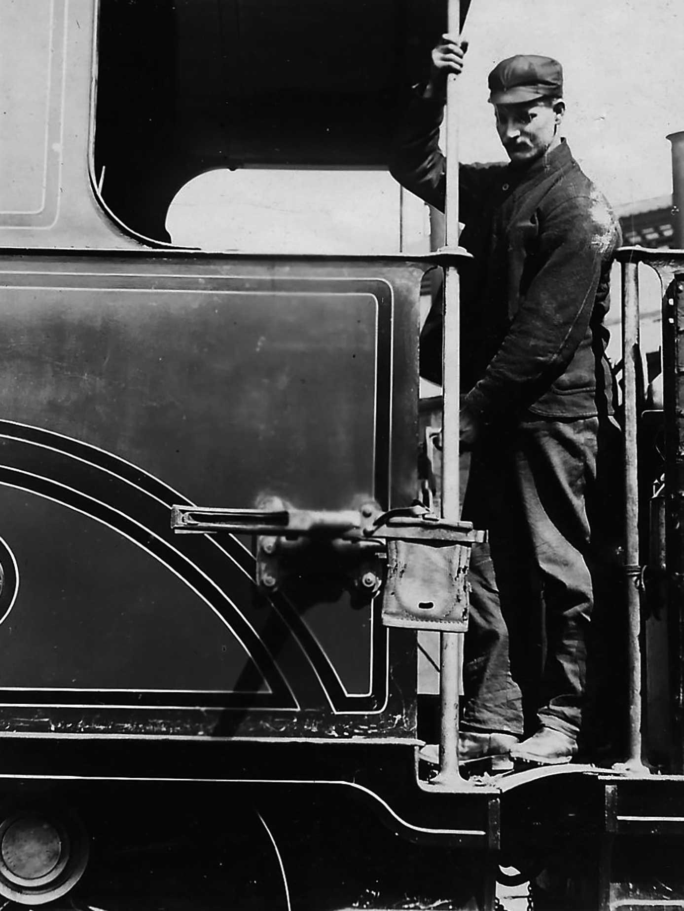
Plate 2/2 Likewise on the footplate of the locomotive, by raising the lever behind the rear driving
wheel splasher, the engine's catcher is lowered from vertical beside the cab side sheet to the
horizontal so as to pass just above the lineside catcher. (Author's collection)
The instructions in the LMS Northern Division Appendix to Working Timetable for March 1937 ufn reads
Manson's apparatus for exchanging tablets consist of a metal standard erected in a suitable position
on the left hand side of both up and down lines. A swinging or sliding lever is placed on the top of the
standard and affixed to the lever in a cross arm with a spring catcher at one side and a delivery spring on
the other side. The engine apparatus is fixed on the left hand side of the engine but the position of the
spring catcher and delivery apparatus is reversed. Apparatus pouches are provided for exchange of tablets or
key tokens. Adaptors are also provided for key token apparatus exchange, the key being secured to the
adaptor before being placed in the pouch. For tablet exchange the pouch must be placed in the catcher with
lid uppermost and for key token exchange the pouch must be placed in the catcher with adaptor downwards.
Manson's apparatus for exchanging tablets or key tokens is provided as shown in the list appended hereto.
[Not reproduced here]
Instructions to Station Masters and signalmen. When a tablet or key token is to be given to the
driver by means of the ground exchanging apparatus it must be fitted in the pouch provided for the purpose
and the pouch placed in the delivery spring of the ground apparatus, care being taken to see that the pouch
hangs plumb. The lever working the sliding arm must then be drawn so as to bring the apparatus fully forward
into position for exchanging and it must be held firmly until the exchange has been made, when the lever
must be promptly reversed to withdraw the apparatus clear of the train. The pouch with the tablet or key
token received from the driver must then be removed from the apparatus and the tablet or key token restored
to the tablet or key token instrument, as the case may be. The tablet catcher must be removed from the
ground standard every time it is used and kept in a convenient place in the signal box or in the receptacle
where this has been provided.
Should the apparatus fail the Station Master or signalman at the signal box in rear must be advised
so that drivers may be informed and be prepared to take the necessary steps to make a hand exchange.
When the exchanging apparatus is situated at the incoming ends of platforms and an exchange is
about to be made by means of the apparatus those in charge must warn any persons standing on the platform
not to approach within 50 yards of the apparatus.
Instructions to drivers. Drivers of trains exchanging tablets or key tokens by the apparatus must,
after the outdoor signals (including the distant signal) have been taken off, fix the tablet or key token
(in the pouch) on the delivery spring of the apparatus upon the engine (care being taken that it hangs
plumb) and place the delivery arm fully into position for exchanging, holding it firmly over till the
exchange has been made. Immediately on the exchange being effected the arm must be withdrawn or raised and
the pouch removed from the catcher. Drivers must be careful to see that the pouch which they pick up from
the ground apparatus contains the tablet or key token for the section into which they are travelling.
As the position of the apparatus varies at the different crossing places and junctions, drivers
must note the positions carefully so as to ensure the safe and proper working of the apparatus.
Until the head on the ground standard was removed, or folded back it was strictly speaking foul of gauge. The Appendix of 1937 under the heading of Oban to Dunblane and branches, when perhaps more generally applicable, therefore contained the following:
Passenger and freight guards must pay particular attention to the closing of carriage and van doors before leaving stations, and also see that loads of wagons which are liable to shift on the journey and come in contact with the token exchanging apparatus are properly secured. Should there be a possibility of a load coming into contact with an apparatus, the guard in charge must instruct the driver to stop the train short of the apparatus and arrange for the apparatus being reversed clear of the train.
Although the Manson system was developed by the GNSR, it is the Highland Railway that is more usually associated with it. Whilst it was undoubtedly an extensive user, with all but shunting engines equipped, this may be due to the fact that it chose to fit the fold down arm mounted on the left hand cab side in preference to the sliding arm from within the cab only visible as an actual exchange was about to take place. More generally classes of locomotive known to have been fitted with Manson tablet exchange apparatus include:
As the LMS introduced new types of locomotives, or classes from other constituents, to replace life expired machines, the tablet exchange apparatus was fitted to those likely to work express passenger or through freight trains. The problem of the wider cabs of the Horwich 2-6-0 Crabs at 8ft 7in was overcome by the neat expedient of attaching the apparatus to the narrower 7ft 1in wide tender near the leading edge. The introduction of Stanier's 5P5F 4-6-0s, some of the earliest examples of which went to the Highland Section in August 1934, at 8ft 6in over both the cab and tender side plates presented a problem not so easily solved. So St Rollox Works completely redesigned apparatus with a shorter arm to fit snugly against the cab-side. The arrangement of the leading fork was amended to be in two parts with the outer vee shaped part directing the pouch to be collected in an inner parallel sided independent piece mounted on a rubber block, which, as the pouch hit the end, caused it to deflect thereby preventing the pouch escaping on the rebound. Later a number of BR Standard Class 5s must have been fitted, including No. 73006.
When diesel locomotives and multiple units were introduced to the Highland lines from 1960, the same design was mounted in a recess created in the body side. The Swindon diesel multiple units' were fitted for Inverness – Aberdeen working. These were operated by the guard and fitted behind a plywood panel in the guard's van. Nonetheless, the greater movement of the bodywork of diesels arising from the bogie's suspension led to an increase in the number of missed catches. This was eventually eliminated on the main line by the introduction of token-less block in the late '60s, nonetheless, exchanges continued elsewhere into the 1970s.
In Northern Ireland, the LMS's Northern Counties Committee adopted the Manson system for much of its single track lines and equipped a high proportion of its front line locomotives with the catcher or 'snatcher' as it was known over there. Photographs indicate that most, if not all, of the following NCC classes of locomotive were fitted on the left hand side with the Manson style of tablet exchange equipment: 2-6-0s: W Nos. 90-93 (all); 4-4-0s: A, B, B2, B3, D, U, U1, U2 (all); and 2-4-0s: G, No. 40's being on the tender. Even J class 2-4-0ST Nos. 25 and 47 were equipped with the arm on the diminutive bunkers sides.
The 2-6-4T WT class, colloquially known as 'The Jeeps', were a special case. The first example No. 5 was fitted with the apparatus on both sides in the conventional position below the rear cab window, but due to the considerable width of the cab, the arm was rather short and hence the head very low down. This meant the fireman had to lean out of the door and reach down to a similar level thereby exposing himself to some risk of danger. As a consequence, subsequent engines had the apparatus fitted to the cab door, and No. 5 in time likewise modified.
Generally, to eliminate further risk of misalignment as a locomotive negotiated a curve with super-elevation, it was found desirable to locate ground tablet apparatus exchange posts on straight lengths of track. Ground apparatus was unlikely to be provided at terminal stations, due to the train being stationary prior to departure, or due to stop upon arrival, the token could easily be passed over by hand either at the platform or as the locomotive slowly passed the signal box. It was also permitted to throw off the tablet as the train passed a signal box at certain locations, including on the NCC: Larne (non-stop trains composed of corridor stock); Larne Harbour; Cookstown Jct; Macfin (non-stop Down Derry Central trains); Coleraine Jct (trains running tender first from Portrush, also trains from Portrush and Derry line at the Down platform); Portrush; and Derry (passenger trains only).
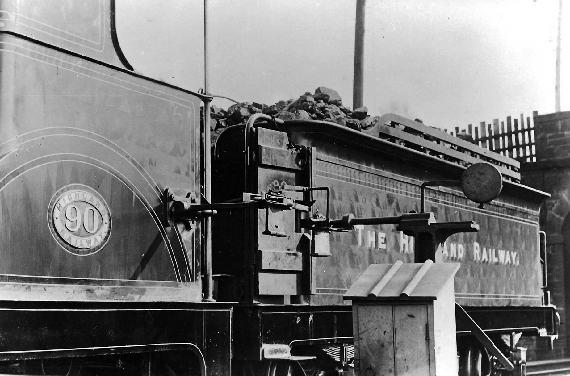
Plate 2/3 As the locomotive, in this case Highland Railway 4-4-0 No. 90 Grandtully of David Jones'
Strath class, passes the leather pouches containing the tablets are delivered and collected by the
lineside and locomotive mounted exchange apparatus. (WO Steel collection, courtesy RJ Essery)
The places at which there are such posts and their positions were listed the Sectional Appendices. The lengths of line and the number of section (Short/long) are given below:
Highland Section:
Callander & Oban Section:
Portpatrick & Wigtownshire Joint:
Northern Counties Committee:
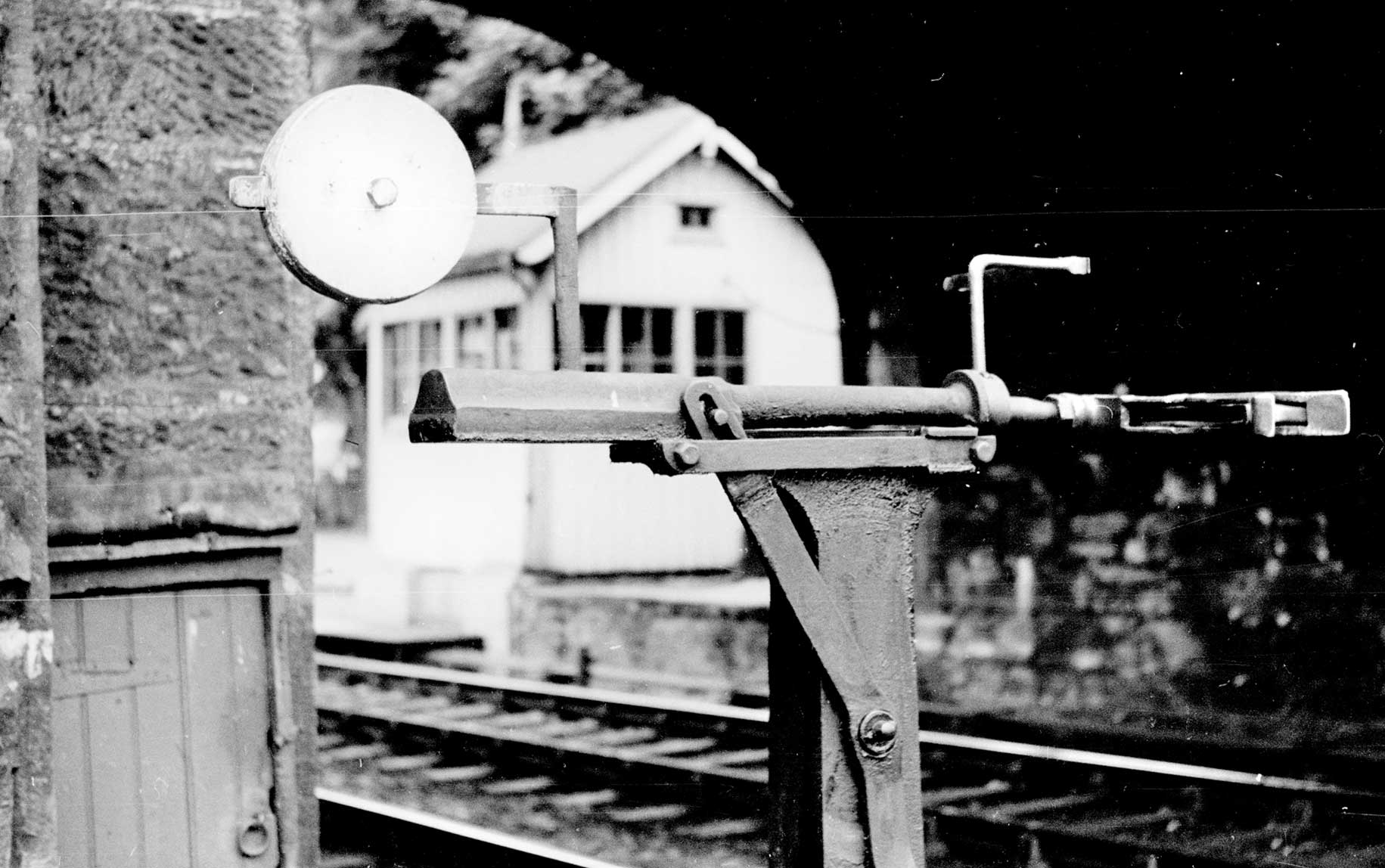
Plate 2/4 A close up of the lineside equipment in the withdrawn position. This was taken at the
country end of Beauly station on 22 July 1959. (Author)
In passing, as well as the above and GNSR lines already mentioned, it should be noted that the Manson system was adopted by the North British Railway in 1911 on the single line stretch between Hillside and Inverkeilor on the line to Kinnaber Jct and Aberdeen for use by only express and fish trains.
The HR and GNSR Manson catchers were reputed to be interoperable, even though the drawings show a difference in height of half an inch, the two having initiated through engine workings from 1906. It has been suggested that the Manson system used on the Highland was dimensionally incompatible with those elsewhere. W Bryson on the drawings submitted with his paper to the Institute of Signal Engineers in 1933 indicated that the catcher was a one and a half inch further out than that used on the Callander & Oban and PP&WJ sections. This is surprising, especially as official drawings clearly state that the Highland's neighbour, the GNSR, set the original standard also used by the C&O and PP&J. Nonetheless, ex-HR engines were transferred to the C&O line in 1934 and, if used, will have had to have their apparatus adjusted and once Stanier's 4-6-0s arrived will not fully operable between the different lines. One can hardly imagine the LMS tolerating such a situation. (See below).
At Moy (HR) there was a unique portable exchange apparatus on the station platform consisting of a heavy base mounted on small wheels running on rails. When run out carefully positioned stops ensured that it had arrived at the correct place.
The NCC apparatus survived longer than most, well into the diesel era. As elsewhere, the diesels caused lots of problems, which the (ex-)NCC tried to solve (unsuccessfully) by reducing the sizes of the tablets and key tokens. A few GNR(I) locomotives were fitted with Manson catchers for working on the NCC.
During the early 1930s the LMS had embarked on major works on the NCC to eliminate the need to reverse trains for Derry and Portrush at Greenisland by constructing a steeply graded cut off between White Abbey and Mossley. This together with re-signalling with colour light between Belfast York Road, Greenisland and Ballyclare Jct, and the introduction of more powerful locomotives enabled journey times to Londonderry/Derry and Portrush to be cut by between 15 and 25 minutes.
To afford minimum of reduction in speed for express and other trains not due to stop on the single line stretches north of Ballymena, the loops at several stations were realigned to provide as straight a run through as practical. For this reason, both loops were signalled for the passage of trains in either direction, whether stopping or not. The distant signals, nonetheless, only applied to the road aligned for fast running. This meant, however, that to utilise the one ground exchange apparatus, the engines had to be equipped with its apparatus on both sides and the ground apparatus to work in either direction. The classes involved include: all the W class 2-6-0s, all the WT class 2-6-4Ts, all the U2 4-4-0s, together with at least some of the As, Bs, Cs and Us. The use of Manson tablet exchange apparatus at these locations allowed tablet exchanges to be carried out regularly at speeds of up to (and on occasion in excess of) 60 mph. The places where this pertained and the loop laid out for fast running were as follows: Ballycarry (Up); Magheramorne (Up); Culleybackey (Down); Glarryford (Down); Killagan (Down); Dunloy (Down); Ballymoney (Down); Macfin (Down); Coleraine (Up); and Portstewart (Down). With running speeds of 60 to 70 mph, this allowed the distance of 34½ miles from Ballymena to Portrush to be covered in 39 minutes.
Although approached by only single lines from four directions all worked by electric-tablet, the strategic junction of Coleraine was re-signalled with 3-aspect colour light signals, the scheme being brought into use on 27 November 1938, see LMS Journal No 22. With the number of signal boxes reduced to just one on the level crossing at the country end and therefore inappropriately located to handle the token exchange for the Macfin to Coleraine section. Instead token-less block working protected by full track circuiting was adopted.
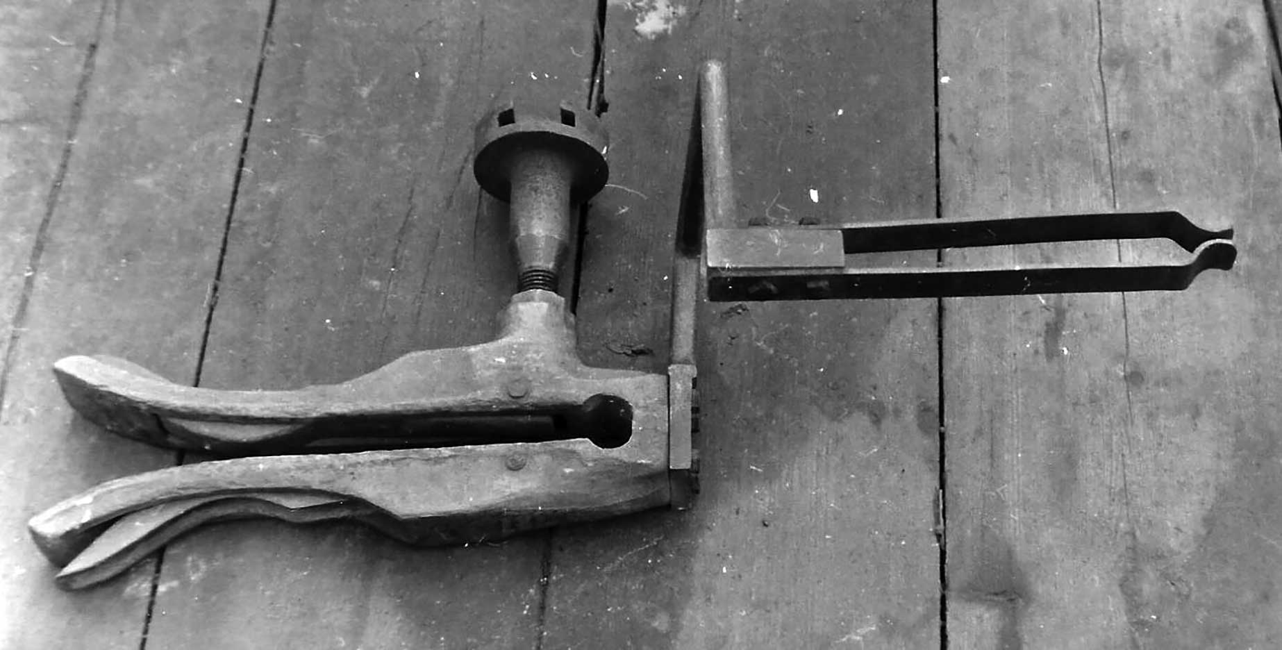
Plate 2/5 The lineside collector fork and spring deliverer detached from the slider on top of the
post. (AA McLean)
During research for this article it became apparent that there is some doubt about the dimensional consistency of the Manson apparatus, as applied to the various lines taken over by the LMS. In particular a discrepancy of 1½ inches in the transverse distance between the centre line of the track/engine and the line of the forks is reported, which with such small tolerances will have been critical.
Although of course not an LMS company, as noted above, Manson introduced his system on the GNSR in 1889 and its application was soon followed by the Highland Railway which was to become a constituent of the LMS. Furthermore from 1906 the HR and GNSR began running their locomotives right through from Inverness to Aberdeen on express services on an alternating basis. It has always been assumed that during such runs advantage would have been taken of using the apparatus to exchange tablets at speed. It has therefore always been taken for granted that the HR and GNSR Manson catchers were interoperable. In addition, excursions from Aberdeen through the Speyside to Boat of Garten and down the Highland main-line to Perth and back to Aberdeen along the Caledonian line, or vice versa, were long a feature of the summers during the inter-war and post war eras. A drawing of the GNSR version, signed by T E Heywood the GNSR Locomotive Superintendent and dated 20 March 1920, is in the author's possession clearly showing this dimension to be 5ft 2in. Furthermore, in 1956 steps were taken by the BR Scottish Region to harmonize the half-inch difference in height between the two systems. This involved a new arm for GNS ground apparatus and an adaptor was GNS engines to reconcile the half-inch, but the means of dealing with any horizontal discrepancy is not apparent.
However, W Bryson in his paper to the Institution of Signal Engineers in 1933 includes various drawings one of which suggests that at that time on the Highland Section the dimension in question had increased to 5ft 3½in, while those used on the Callander & Oban and PP&WJ sections remained at the original 5ft 2in, thereby rendering the Highland's fittings incompatible with those elsewhere. This must have meant that when the ex-HR engines (all eight Clans and a pair of Castle class 4-6-0s) were transferred to the C&O line in 1934, if it were to be used, they will have had to have their apparatus adjusted. It is understood that, as young man at St Rollox, the late Duncan Burton and former HMRS and LMS Society member is recorded as saying he had been involved in carrying some work in such a connection, or could this have been in connection with the new design necessary for the Stanier 4-6-0s?
The question is what adjustments might St Rollox have undertaken? It would seem short sighted merely to add or subtract 1½ inches to the length of the arm as and when locomotives moved back and forth from the Highland to other sections. The LMS practice of employing locomotives on an intensive 'common-user basis' would never have readily accommodated such a situation, especially once the wide ranging Stanier 4-6-0 Black Fives came on stream in any numbers.
To achieve network wide consistency, the equipment on the locomotives and ground apparatus of one standard will have to be altered to conform to the other. With the PP&WJR Section's equipment apparently no longer in regular use and with the passenger trains on the C&O calling at most stations, the utilisation on the Highland Section must have far out-weighed them both. This suggests that it will have been much more efficient to convert to the Highland's standard, or forgo their use elsewhere altogether, until of course, as will be related, World War 2 intervened.
Perhaps readers have more information and can comment on this aspect, via the link.
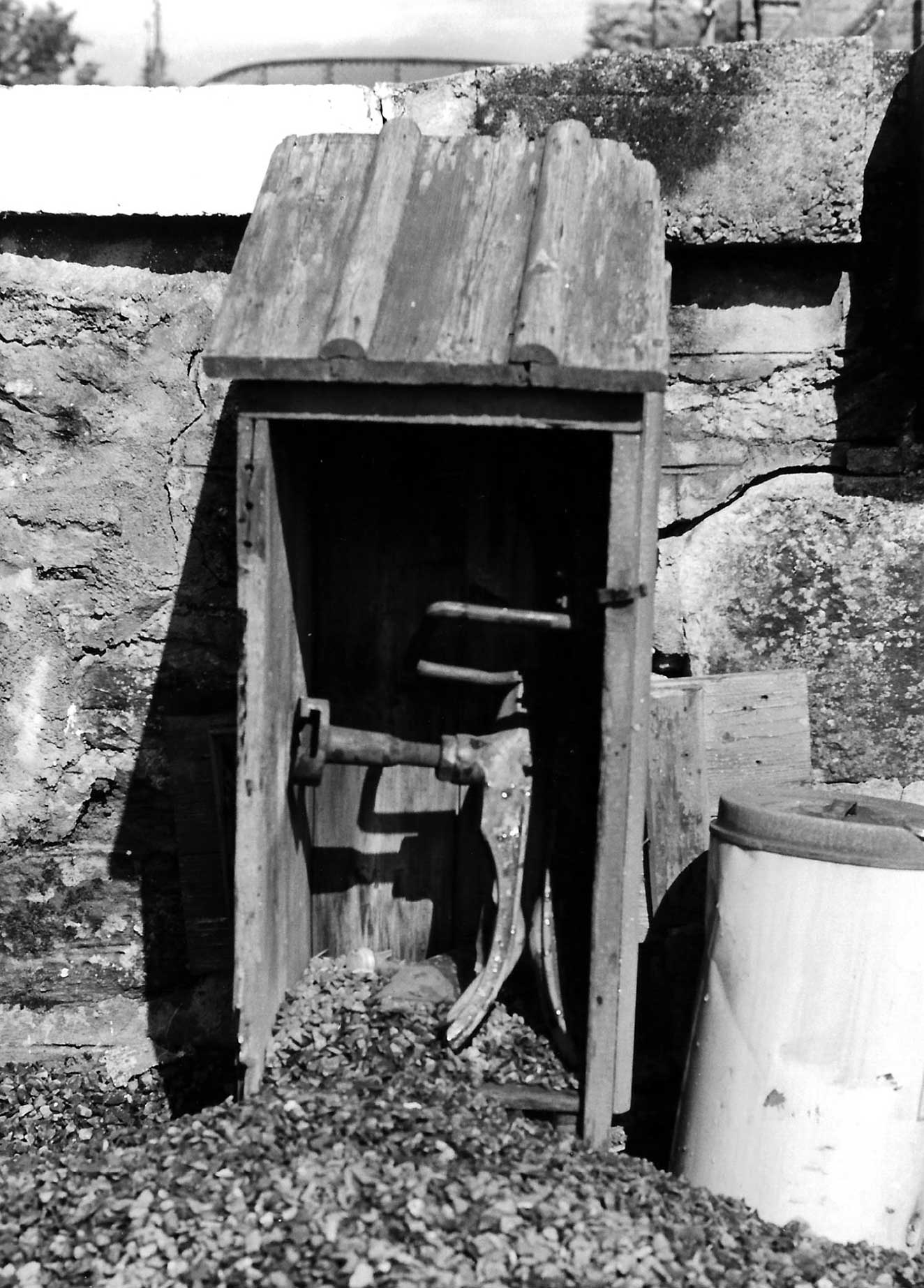
Plate 2/6 The lineside collector/deliverer safely put away in its cabinet close to the post, but
lacking a door. Taken at Lairg on 21 August 1979. (Author)
At the time of the development of the automatic tablet exchange apparatus named after him, James Manson was Locomotive Superintendent of the Great North of Scotland Railway. He had been born at Saltcoats, Ayrshire in 1845. Following his schooling, he started an apprenticeship on the GSWR under Patrick Stirling at Kilmarnock Works on 23 September 1861 and continued his training under James Stirling once his brother left for the GN at Doncaster in 1866. Three years later, to further his career, he took a position with Barclay, Curle & Co, Glasgow and later sailed with the Bibby Line as a marine engineer, before returning to the GSWR at Kilmarnock by then under Hugh Smellie's superintendence, gaining the position there of Works Manager.
In October 1883 Manson filled the vacancy created by the retirement of William Cowan as Locomotive Superintendent of the GNSR at Kittybrewster, Aberdeen. As well as introducing some graceful 4-4-0 locomotives, in 1886 Manson developed the ideas of John Duncan for the automatic tablet exchange apparatus and for which he declined to take out a patent on the basis that as a safety feature all should be encouraged to take it up.
On 1 September 1890, following the departure of Smellie for the Caledonian Railway, he returned to his home territory, where, before his retirement at the end of 1911, he introduced a variety of handsome designs, many of which were still in front line service when the LMS took over in 1923. He died aged 89 at Kilmarnock on 5 June 1935.
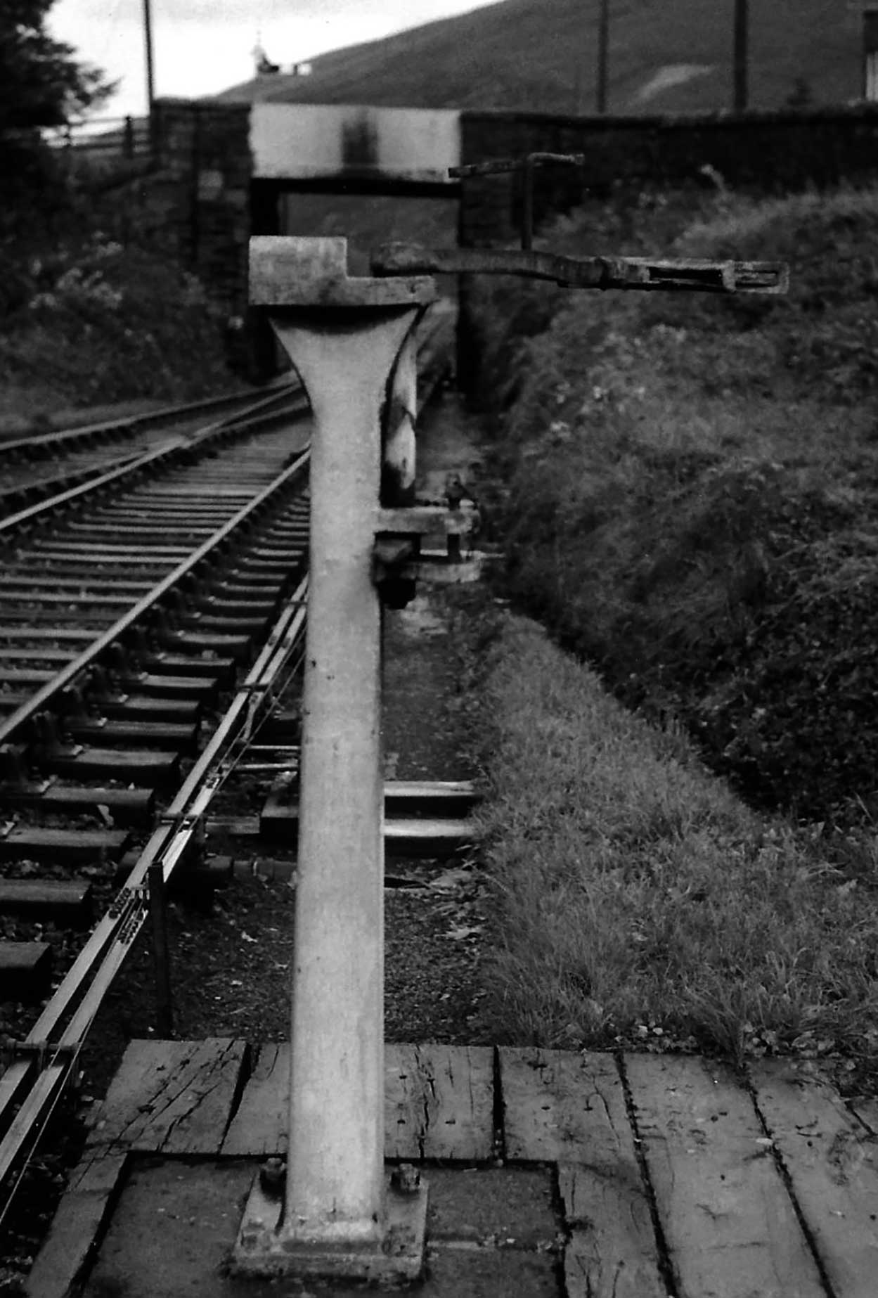
Plate 2/7 The alternative form of Manson post at Strathyre as adopted on the Callander & Oban
line with a swivel arm, here in the retracted position. (N Forrest, courtesy Transport Treasury)
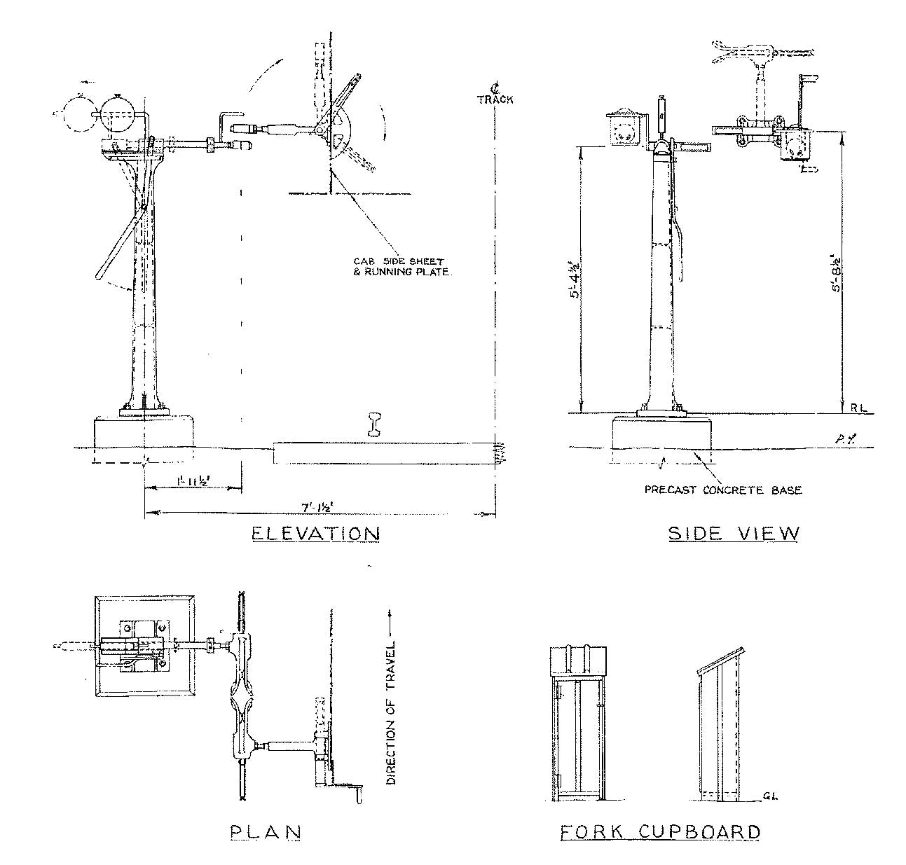
Figure 2/1 Manson tablet exchange apparatus as applied to the Highland & Portpatrick &Wigtonshire Joint Sections. (Author)
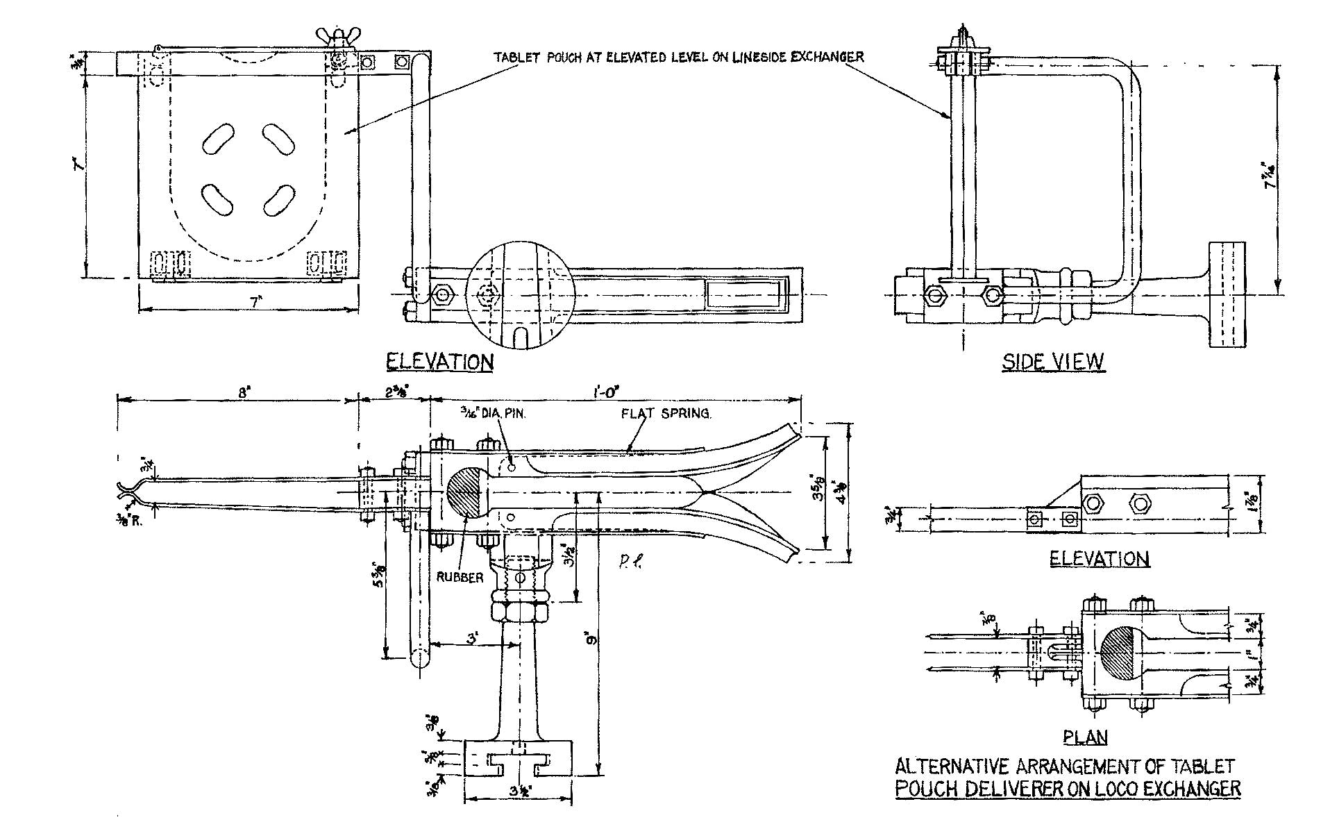
Figure 2/2 Manson tablet exchange apparatus as applied to the Callander & Oban lines. (Author)
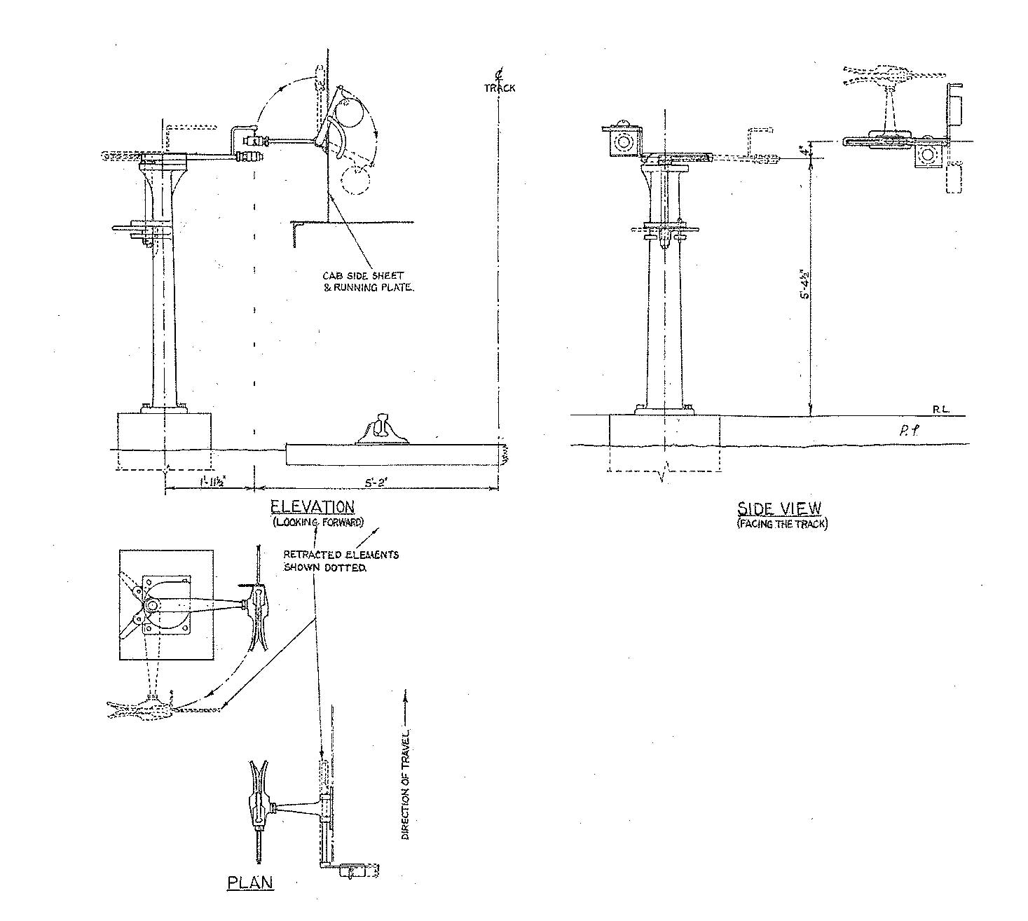
Figure 2/3 Manson tablet exchanger head for lineside apparatus, together with variations for locomotives. (Author)
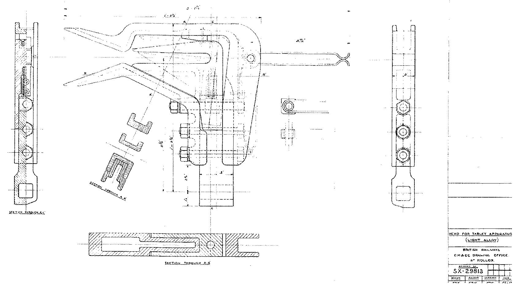
Figure 2/4 Modified design of catcher for Manson apparatus by St Rollox necessary for wider Stanier engines. (BR, Sc. Reg, courtesy G Warburton)
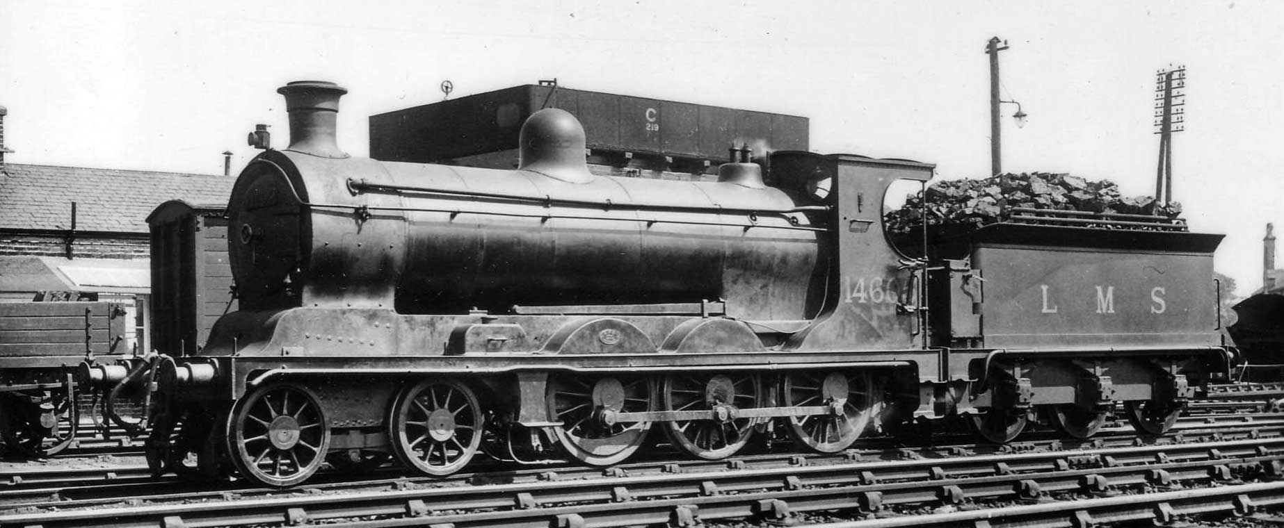
Plate 2/8 The fold down form of Manson apparatus fitted to ex-CR 4-6-0 55 Class No. 14605 for use on
the Callander & Oban line. (Author's collection)
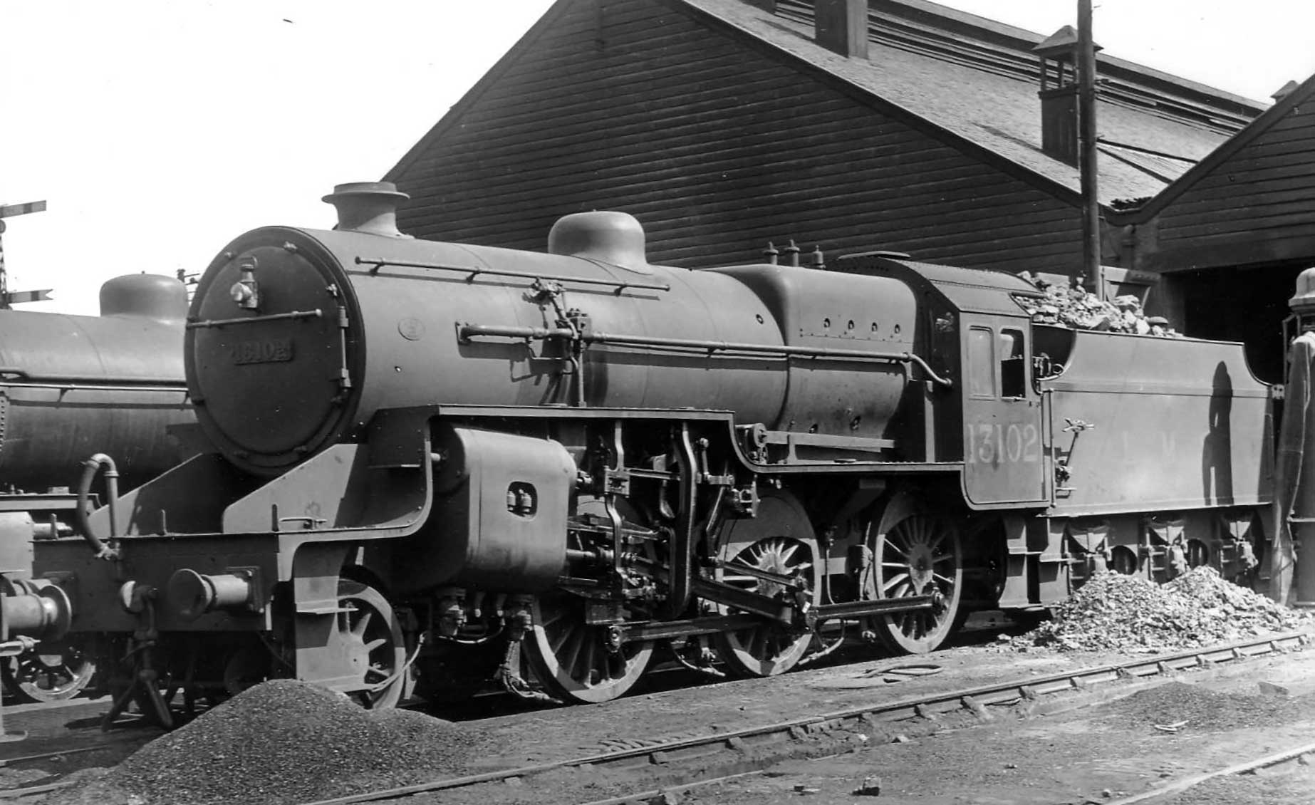
Plate 2/9 Although the cab of the LMS 2-6-0 Crabs Nos. 13100 to 13109 allocated to the Highland
Section were too wide to accommodate the original form of Manson fold down apparatus used up to that
time, the tender was found to be sufficiently narrow to permit it to be fitted, as shown on No. 13102 at
Perth Highland shed. (TG Heburn, courtesy Rail Archive Stephenson)
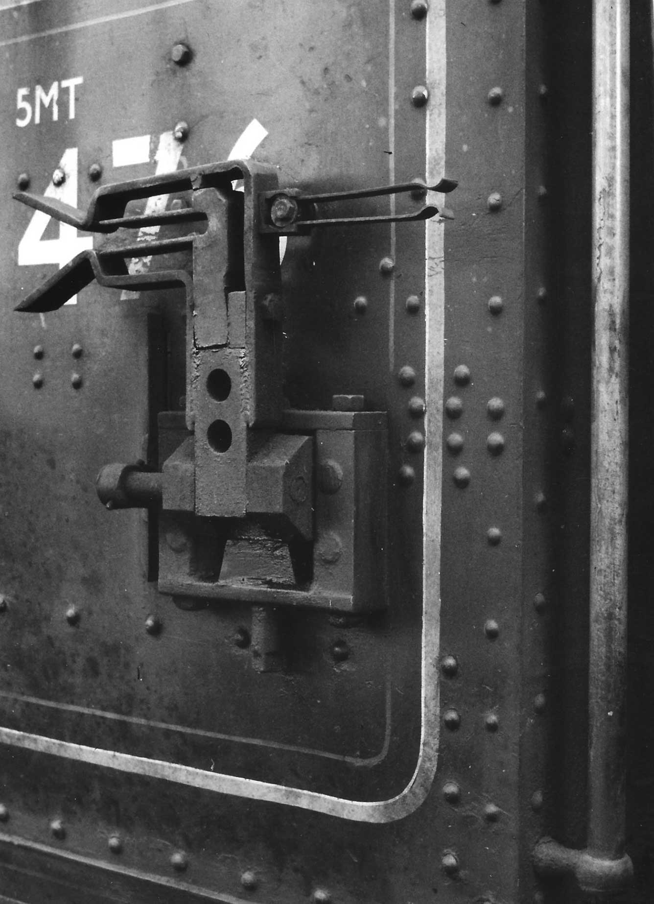
Plate 2/10 The St Rollox designed Manson collector mounted on the cab-side of ex-LMS 4-6-0 5P5F No.
45476 at Inverness on 21 July 1959. The operating lever passes through a slot to the left. (Author)
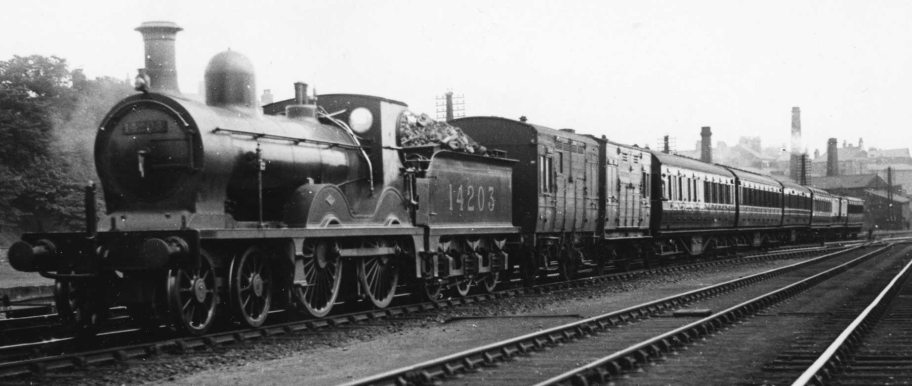
Plate 2/11 The Manson system of tablet exchange apparatus was used on the Portpatrick &
Wigtonshire Joint Railway between Castle Douglas and Stranraer, but fell out of use soon after the LMS
took over due to the wider variety of engines rostered, not all of which were suitably equipped. Here
No. 14203 of the ex-GSW 336 class heads out of Carlisle still so fitted. (David Stirling
collection)
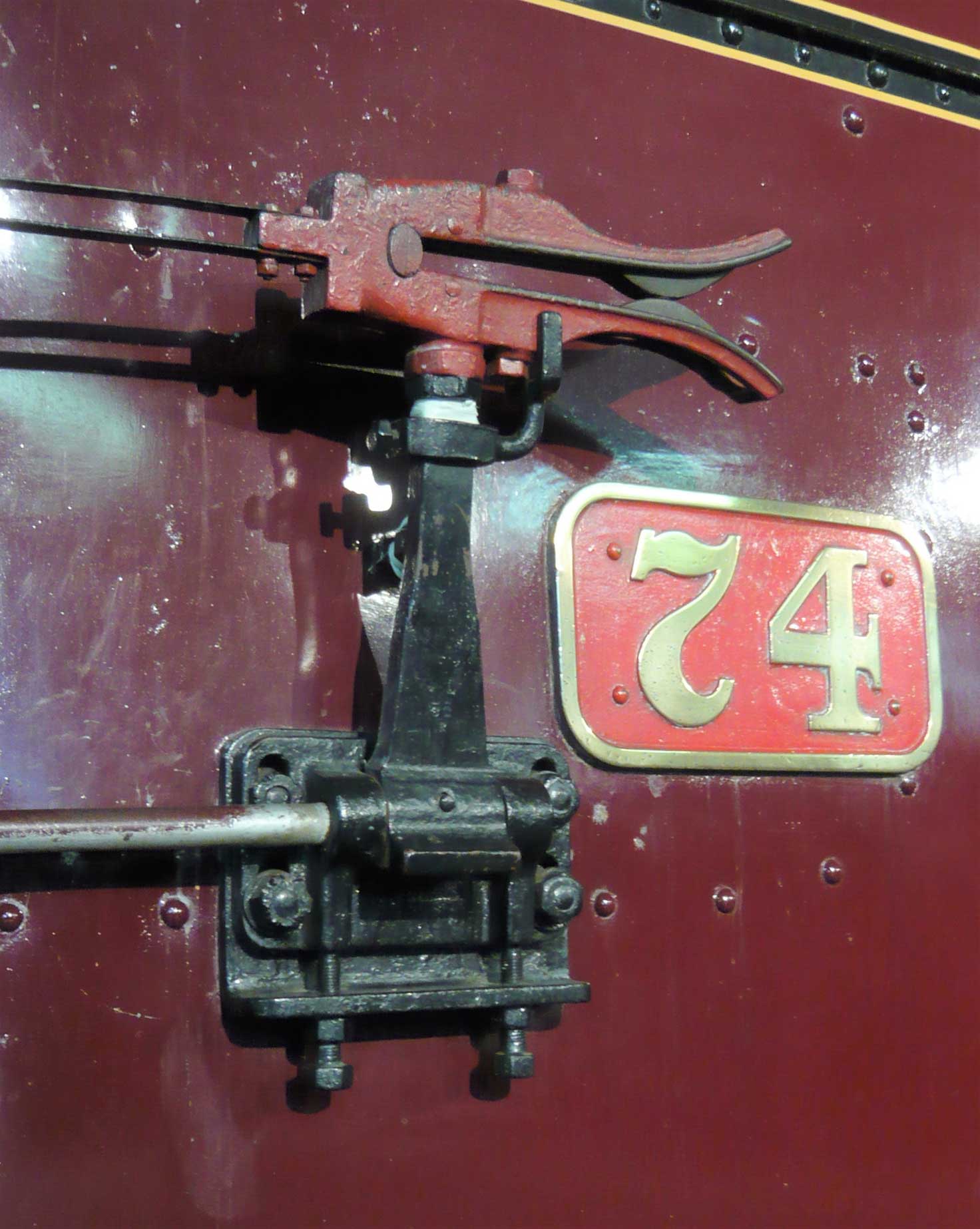
Plate 2/12 The Manson style tablet snatcher on the right-hand side of ex-LMS Northern Counties
Committee 4-4-0 No. 74 Dunluce Castle, now preserved at the Ulster Transport Museum, Culter outside
Belfast. (Author)
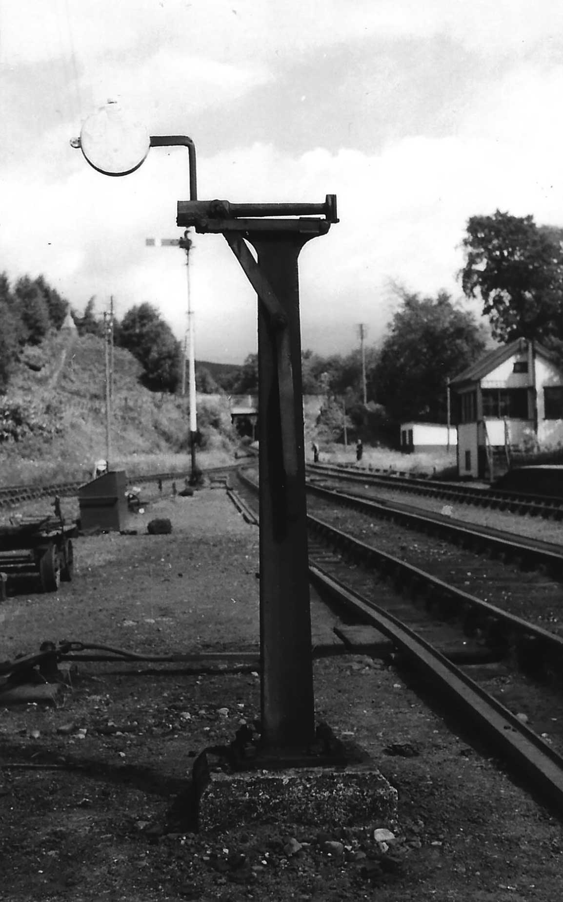
Plate 2/13 Line side post for Manson apparatus at Garve. (Author)
Site contents Copyright © LMS Society, 2024
April 18th, 2024
Site contents Copyright © LMS Society, 2024