

This site uses non-intrusive cookies to enable us to provide a better user experience for our visitors. No personal information is collected or stored from these cookies. The Society's policy is fully explained here. By continuing to use this site you are agreeing to the use of cookies.
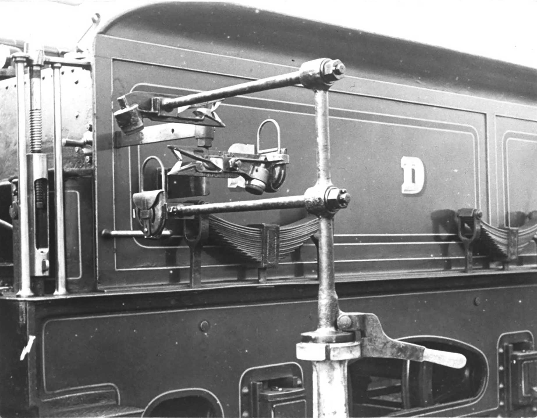
Plate 3/1 A staged picture of the tender of a locomotive about to pass the lineside apparatus of the
Whitaker system and exchange the tablets by the catchers engaging with the small hoops on top of the
pouches. (S&DJR, courtesy Peter Cattermole)
Following an accident to the fireman during the hand exchange of tokens on the Somerset & Dorset Joint Railway at Midford on 10 September 1904, Alfred Whitaker, the Locomotive Superintendent of the line, began to give consideration to a mechanical means of fully automatically exchanging tablets at a greater speed than was safe by hand methods. He will have been aware of the Manson system initiated on the GNSR, which had also been adopted by the Highland Railway and on the Callander & Oban line, but felt that while in use the extremities of the apparatus being foul of gauge was unacceptable and was not returned to be clear of gauge without the input of man. He was, therefore, determined to devise a method that automatically returned some of these elements to within gauge as soon as the exchange had taken place.
As the system was developed, various prototypes were tried out on the Bridgwater branch. Production versions of his apparatus were brought in general use on the single-track sections between Bath Junction and Wimborne Junction, and the 'cut-off' line to Broadstone Junction, from 27 March 1905, at nine stations and on 71 locomotives at cost of £245. In this form, exchanges could satisfactorily be carried out at a speed of up to 60 mph, thereby achieving a seven-minute reduction in running time between Bath and Bournemouth. A patent for the design was applied for and granted in 1905, No 861.
In May 1906 the Midland & Great Northern Joint Railway also decided to adopt the Whitaker system, bringing this into use the next year at a total cost of under £1,800 including the royalty fee. This was followed in early 1908 by the Midland Railway on its line between Bourne and Saxby so that single track lengths on the route between Peterborough and Cromer were equipped throughout. The components were made in works at Highbridge (S&DJR) or Melton Constable (M&GN), while the Railway Signal Co was licensed as sole manufacturers for use elsewhere.
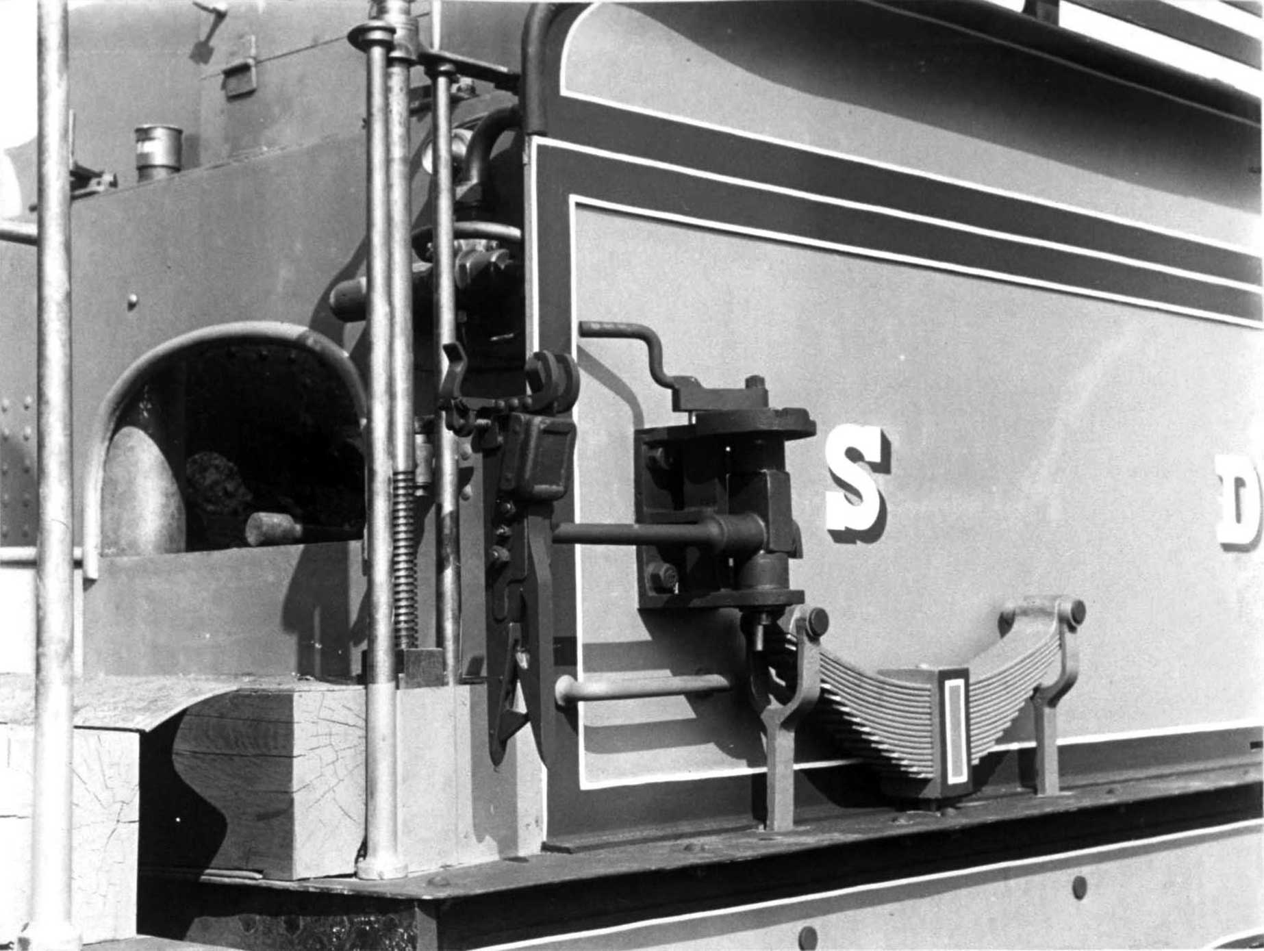
Plate 3/2 The final version of the engine exchanger with a vertically hinged mount and rotating a
catcher head in the normal position with the head pointing downwards. (S&DJR, courtesy Somerset &
Dorset Railway Trust)
The ground mechanism consisted of a cast-iron standard, which was located as near to the running line as the structure gauge permitted and bolted down to a substantial timber projecting from the track. Into this was fitted a vertical wrought-iron spindle carrying one or two horizontal arms, in the case of the latter one above the other. Across the end of the upper arm was a pick-up jaw while the lower arm supported a delivery spring clip. The spindle could be rotated by the action of a pair of bevel gear wheels and a weighted lever, so that the arms were turned through 90 degrees to be either parallel with the running line when not in use, or at right angles directed towards the line when in operative position. This was operated by the signalman either at ground level by hand or by a system of wires, pulleys and cams remotely from the signal box.
On the engine or tender the combined receiver and collector apparatus was usually fixed onto a horizontal slide-bar mounted transversely in a cast iron guide inside the locomotive or tender. The slide bar passed through the cab or tender side-sheet and on its outer end was fitted a combined pick-up and delivery clip.
The final version of the engine exchanger, only able to be fitted to narrow tender sides, was in the form of a vertically hinged mount with a catcher head, capable of rotating from the vertical position when against the side of the tender out of use, to horizontal when the arm was moved out ready to make an exchange. This version may have been developed to reduce the risk of the sharp end of the head entangling itself on any passing object and appears only to have been fitted to some S&DJR engines.
Derby also designed a temporary exchanger capable of being clipped to the tender of foreign locos. It is known that several BR Standard 4-6-0s were so treated.
The receiver on both the ground and locomotive was in the form of a jaw with three spring-controlled fingers and a rubber buffer at the inner end of the fork, together with a 4 by 3 by 1½ inch soft rubber pad on the underside and to the rear of the jaw to cushion the blow from the pouch as it swung back having been collected. The jaw for the locomotive was at first cast in brass or gun-metal, but later in aluminum alloy; but in cast-iron for the ground apparatus. On the locomotive the delivery clip was mounted immediately behind the receiver jaw, whereas on the ground it was on the arm at the upper level. The alignment of each was so designed that the receiver collected the hoop of the pouch from the deliverer as the locomotive passed.
Ordinarily when not in use the deliverer and receiver apparatus on the locomotive was withdrawn so that it was tight against the side sheet of the engine or tender. To bring into use, one of the enginemen would either slide the arm outwards or hinged it backwards so that the apparatus lined up with that on the ground and ready to exchange tokens. The mount was adjustable so that the correct height could be maintained when compared with a special gauge located at Highbridge Works. Once received, the pouch was removed from the catcher, so that the driver (or fireman) could check that it was the correct one for the section, and then placed safely on a hook in the cab until it was time to put it back on the apparatus prior to delivery at the next block-post.
When not in use, the arms of the ground apparatus were folded back clear of the structure gauge. Prior to the arrival of a train with which tablets were to be exchanged, the signalman would place the pouch containing the tablet for the next section on the deliverer and swing the arm(s) through 90 degrees so that the tablet was held in the collecting position. Once the exchange had taken place, the combined or receiving arm was returned to be parallel to the track, automatically in later versions, a feature not found with other systems. This was achieved by the impact of collecting the tablet disturbing the counter-balance arm causing it to fall downwards by gravity and rotate the vertical shaft by means of the bevel gears.
To affect an exchange, each tablet was first placed in a pouch with a steel wire handle on top and hung from a clip either mounted on the delivery arm of the lineside equipment or behind the collecting jaws of the locomotive. Early versions of the handle on top of the tablet pouch were circular hoops, but the M&GN adopted near square 5-inch loops with merely rounded corners, giving a lateral tolerance of 2 inches either way. In the vertical direction the jaws had an opening of 3¾ inches to allow for variations in ride height of the locomotive or tender, due to being fully loaded with coal and water or near empty together with some allowance for wear and deterioration of the springs etc.
Ordinarily the apparatus was sited on the left-hand side of the locomotive and track. At intermediate passing loops there would be a combined ground deliverer/receiver adjacent to each loop line, so that an engine could give up the tablet for the section which it had left and pick up the tablet for the next section at the same time. Where a train was running from a double-track line onto a single-track line then only a ground deliverer would be necessary, with a corresponding separate ground receiver on the other side of the line for trains coming off the single-line section. At a single-line terminus, unless the signal box was close by, hereby permitting manual hand over, a similar situation might exist. The options available for design of the lineside elements of the Whitaker system catered for these two eventualities.
At Templecombe No. 2 Jct, in earlier days at Corfe Mullen Jct and Holbeach West (M&GN), however, the close proximity of adjacent running lines on the left-hand side led to the design and installation of a special collapsing derrick or 'falling man' type of collector located in the 'six-foot' between the running lines, rather than in the 'cess' beside the line. This consisted of a receiver at the top of a hinged pole, which, when in use, was held upright by being just past the point of balance and was forced down by the passage of the train and locked to prevent it rebounding. When not in use, it remained folded down to below the equivalent of platform level.
Some time after S&D passenger trains ceased running to Wimborne in 1920, perhaps not until subsequent cessation of goods traffic in 1933, the 'falling man' at Corfe Mullen was transferred to Bath Junction, probably sometime between 1924 and 1933. This was an additional post provided solely for use with arriving Up trains that were running 'wrong road' on the Down Branch in order to access the Goods Yard. Otherwise, all other Up trains arriving on the Up Branch used a normal fixed ground receiver in the cess. In contrast, at Templecombe No 2 Jct the 'falling man' was the only receiver for Up trains coming off the single-line from the south.
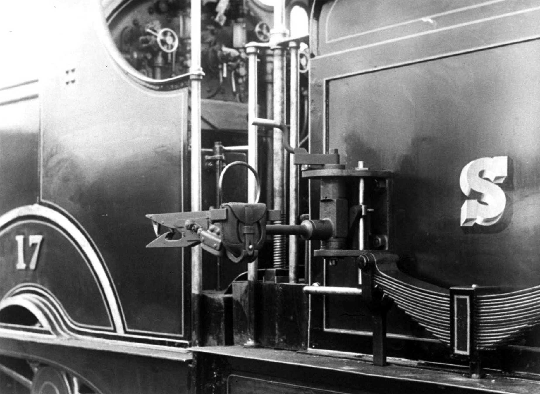
Plate 3/3 The same version of exchanger in the extended position ready to make an exchange.
(S&DJR, courtesy Peter Cattermole)
The places at which there are ground tablet apparatus exchange posts and their positions were listed the Sectional Appendices. The stretches of line and the number of section (Short/long) are given below:
The line from Corfe Mullen Jct to Wimborne Jct was closed in 1933, whilst the passing loop at Stourpaine, between Blandford and Shillingstone was taken out of use in 1951.
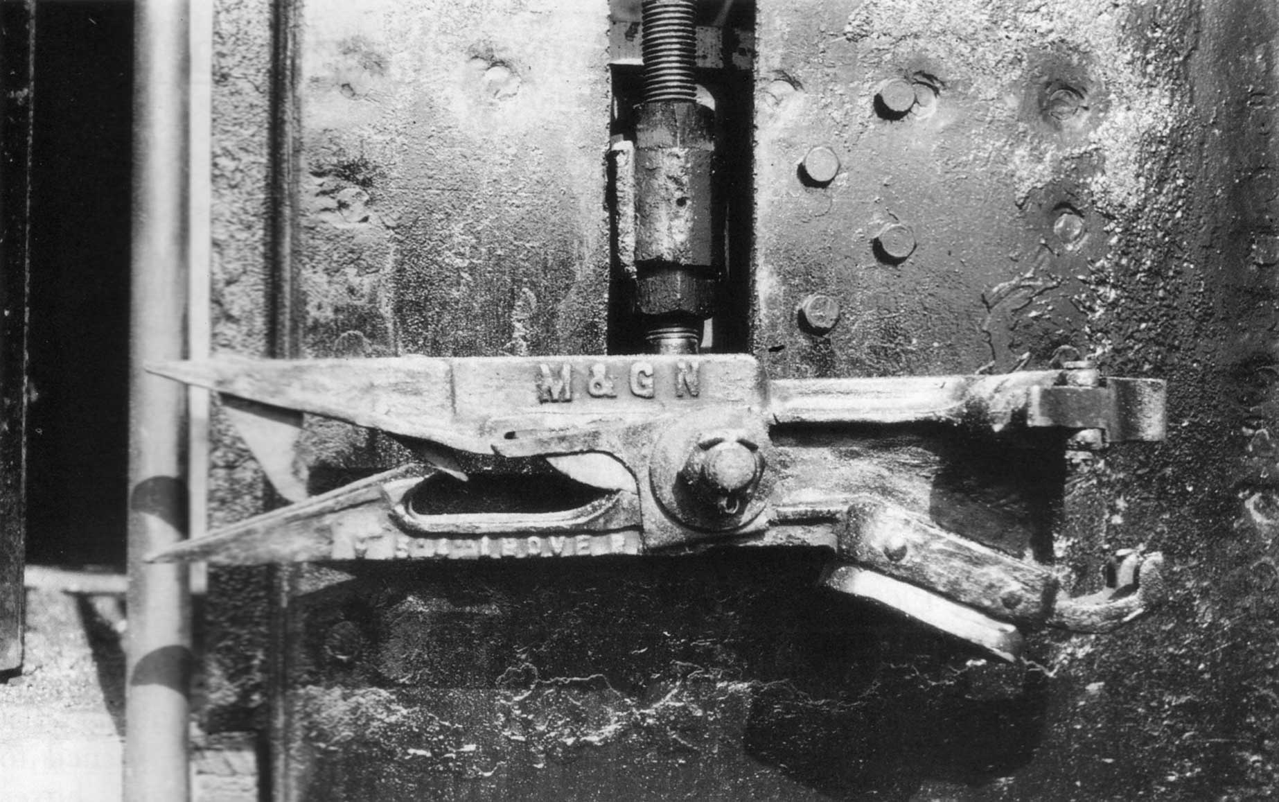
Plate 3/4 Whitaker tablet catcher fork of the non-rotating type on an M&GN engine in retracted
position. Note the slot cut in the tender side to accommodate the apparatus within the loading gauge when
not in use. (RE Vincent, courtesy Transport Treasury)
Most of the S&DJR's indigenous locomotives used on main-line work will have been provided with the equipment, while following the take over of the line's motive power activities by the LMS in 1930, the locomotives drafted in to replace those withdrawn will have had it transferred to them.
Photographs indicate that most, if not all, of the following SDJR classes of locomotive were fitted on the left-hand side with the Whitaker style of tablet exchange equipment:
Of the 2-8-0s 7F Nos. (80-90), 9670-80 in 1932 renumbered 13800-10, due to a lack of suitable turntables, the initial batch of six Nos. 80 to 85 were originally fitted with tender cabs for running in reverse direction for considerable distances. For this reason they were all also equipped with tablet exchange apparatus on both sides.
From 1906 all M&GN tender and tank engines were fitted on both sides that on the right hand side facing backwards, to permit exchange while running in either direction.
Those other locomotives drafted in to work these lines known to have been fitted with Whitaker's apparatus included:
In crossing the Mendip Hills, heavy freight trains were usually banked up the steep grades to Masbury Summit on the double-track main line. In the case of Down trains, although there was a signal box just over the summit at Masbury, this was only opened for peak traffic being 'switched out' at other times. So instead of the banking engine continuing to Winsor Hill or Shepton Mallet (about three and a half miles) before crossing over to the Up line, it dropped off from the rear of the train at Masbury Summit and ran back 'wrong line' one mile to Binegar. To protect this movement, even after the main train going forward had cleared the section ahead (whether to Masbury, Winsor Hill or Shepton Mallet), the banking engine collected a special 'bank engine staff' as it passed Binegar. This staff was a large metal key kept in a lock attached to the lever-frame in Binegar signal-box; its removal from the lock prevented the signals for the section being cleared again for another train until the banker had returned to Binegar and the key had been restored to the lock. To avoid the need for a banked Down train to slow down or stop at Binegar to collect this staff, a slightly modified Whitaker deliverer post to accept the bank staff was provided at Binegar and all the regular bank engines were equipped with a Whitaker receiver. On its return journey from Masbury Summit the banker would cross over to the Up line at Binegar, where the signalman would collect the staff by hand, and then the engine would return 'right line' to Radstock at the foot of the incline. The bank engine on the climb out of Bath on the other hand relied on a hand exchange of the banking staff.
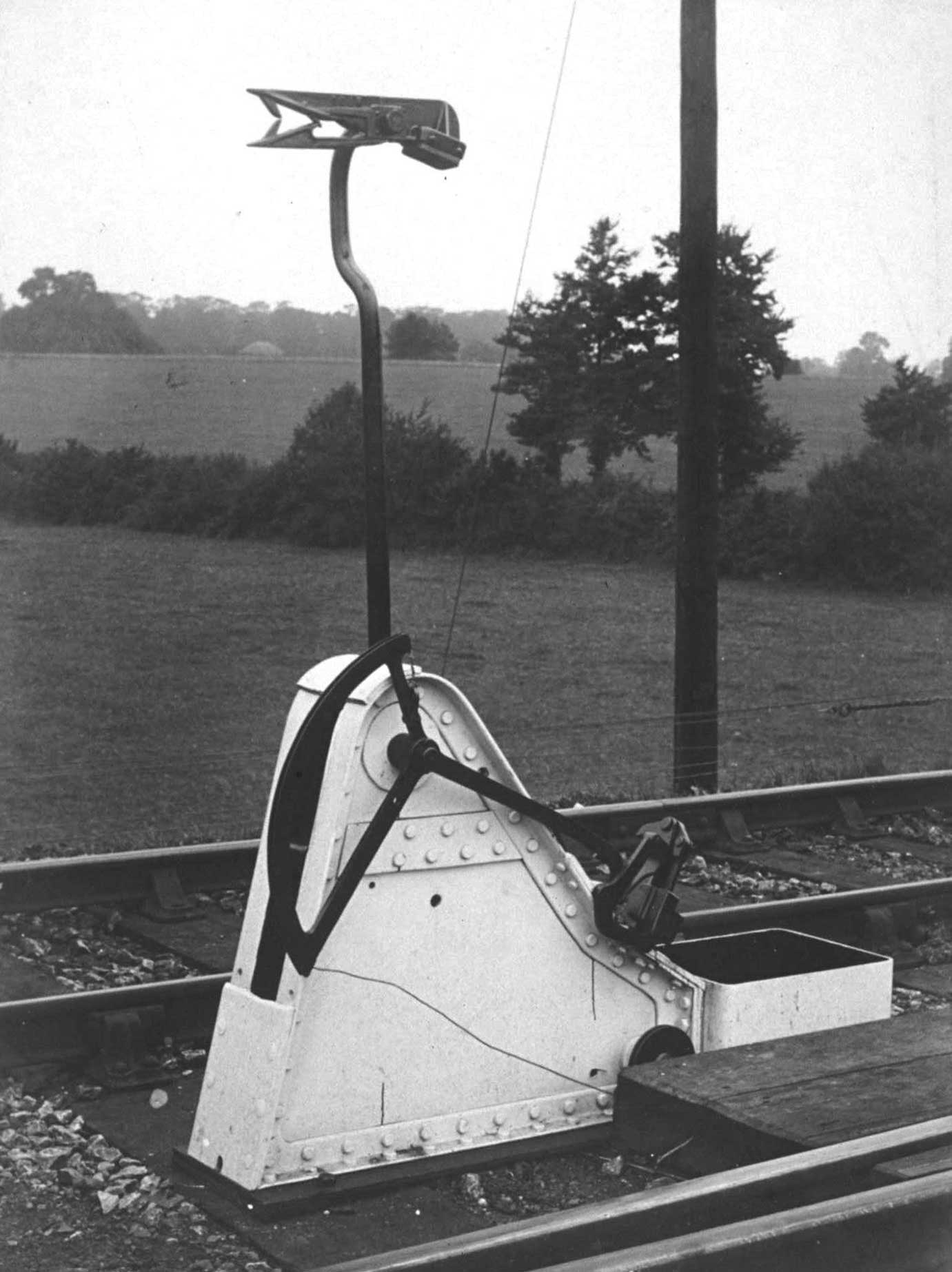
Plate 3/5 Special 'falling man' tablet receiver for use in the 'six-foot' between tracks, which folds
down when not in use so that this and the white painted support are below platform height. (S&DJR,
courtesy Peter Cattermole)
There are several stories of "misses" when locomotives have failed to pick up the tablet from the tablet-exchange apparatus, with the result that the tablet landed on the roof of adjacent Hope & Anchor public house or in nearby gardens. It is reported that on at least two occasions it was, apparently, lost without trace. In 1932 out of around 350,000 exchanges on the M&GN only 62 dropped tablets were recorded, while 140 pouches were repaired, 60 hoops renewed and 80 straightened. Nonetheless, the small size of the hoop to the pouch to be collected meant that the tolerance for error was not great. Variations in the height of the locomotive due to weakened springs aggravated by sway of the locomotive due to undulations in the track could lead to missed catches. By 1936 the Chief Operating Manager of the LMS was sufficiently concerned to ask the Engineering Section of the Research Department at Derby to investigate the failure of the tablet exchange apparatus which had been occurring in service on the Bath to Bournemouth portion of the Somerset & Dorset Joint Railway.
A series of on site observations was taken of all exchanges in the Up direction at Stourpaine throughout a whole day, a record being made of the numbers and particulars of the locomotives making the exchange. Cinematic photographs were taken from the lineside of the exchanger in directions of parallel and normal to the track.
A second set of observations was undertaken of all the exchanges made by locomotive No. 699 working in both Up and Down directions between Bath and Bournemouth. These included a photographic record from the engine again in the longitudinal and transverse directions. Those in the first were taken by an operator and his camera housed in a special shelter erected on the side of the locomotive, while those in the transverse were necessary in somewhat oblique direction from the cab.
A third series of observations was made of a temporary type of exchanger specially fitted for the purpose to locomotive No. 699, details of which remain obscure, but perhaps of the nature of an interim solution to the problems encountered with the permanent type mentioned below.
A high-speed camera taking 64 frames a second was used to record this large number of actual tablet exchanges between the locomotive and the fixed exchanger. The resulting film was then examined with the action of the process projected at quarter of the speed of the actual exchanges.
Preliminary conclusions suggested that at high speed the pouch entered the catcher with such energy that the steel hoop at its top rebounded off the rubber cushion in the crutch with such force that it escaped the sprung tongues intended to contain it. Unfortunately the rest of the report has yet to be found by the author.
After the Western Region took over the S&D from Bath to Templecombe, suggestions were made that there was a worrying increase in the number of misses on their limited length of single line, and investigations were undertaken into changing the S&D over to the Manson system. However, this was to overlook that the majority of Whitaker exchanges took place south of Templecombe administered by the Southern Region. This therefore ignored the cost of converting these as well or accepting the time that would be lost by doing without. As a result, nothing came of the matter. In passing it should be noticed that the GWR, of course, had since the thirties, experience of its own Whitaker exchangers on both the Norton Fitzwarren to Barnstaple and Norton Fitzwarren to Minehead branch lines. The apparatus was manufactured by the Railway Signal Co to a modified design. As a consequence, they presumably had less than perfect regard for it.
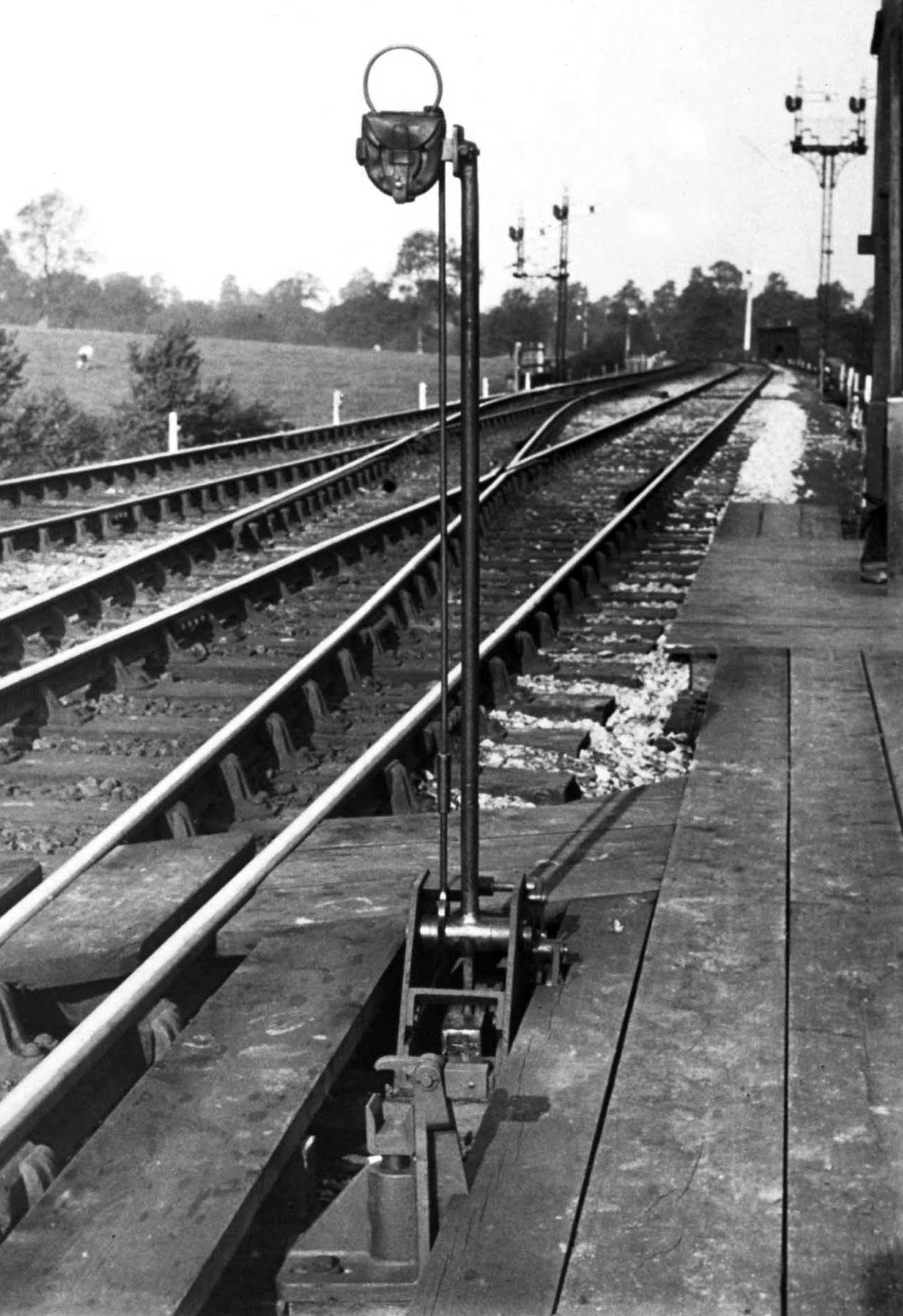
Plate 3/6 Another special 'falling man' tablet deliverer for use adjacent to a cross-over which
collapses between foot-boards and below rail level when not in use at Templecombe. (S&DJR, courtesy
Peter Cattermole)
Alfred Whitaker was born in July 1846. He joined the Midland Railway in 1860 serving under the Locomotive Superintendent Matthew Kirtley. In due course he was placed in charge of several engine sheds in the north, before being appointed Locomotive, Carriage & Wagon Superintendant of the S&DJR in November 1889 on a salary of £375 per annum. While there he was responsible for not only the introduction of the tablet exchange apparatus that bears his name, but also the rebuilding of the Highbridge Works and installation of new machinery and plant and various other innovations. Retiring in 1911, he passed away on 5 March 1938 at the age of 91.
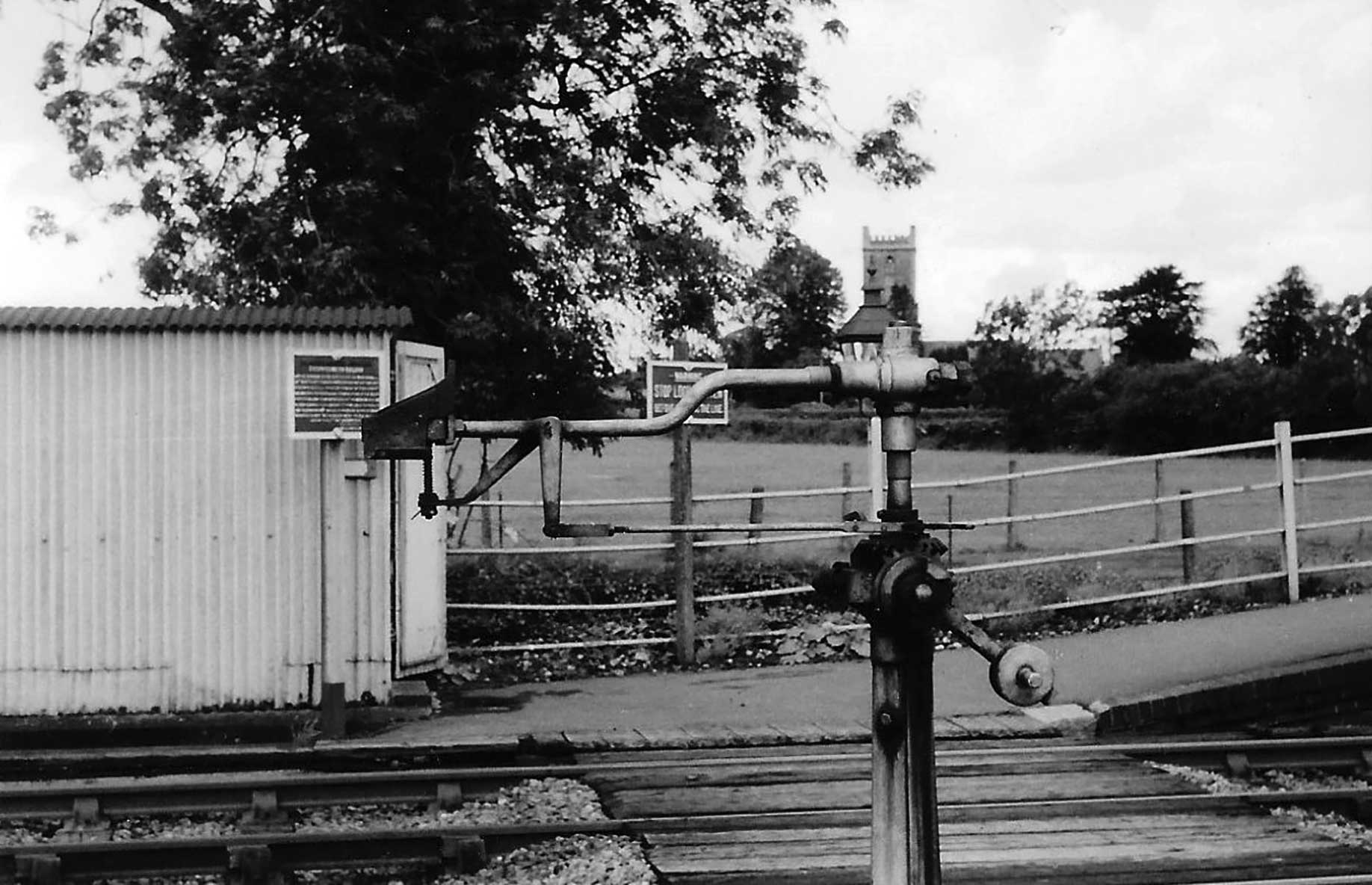
Plate 3/7 The deliverer apparatus for staff from banking engine at Binegar (S&D) with the lamp room
and church in the background on 2 August 1958. (Author)
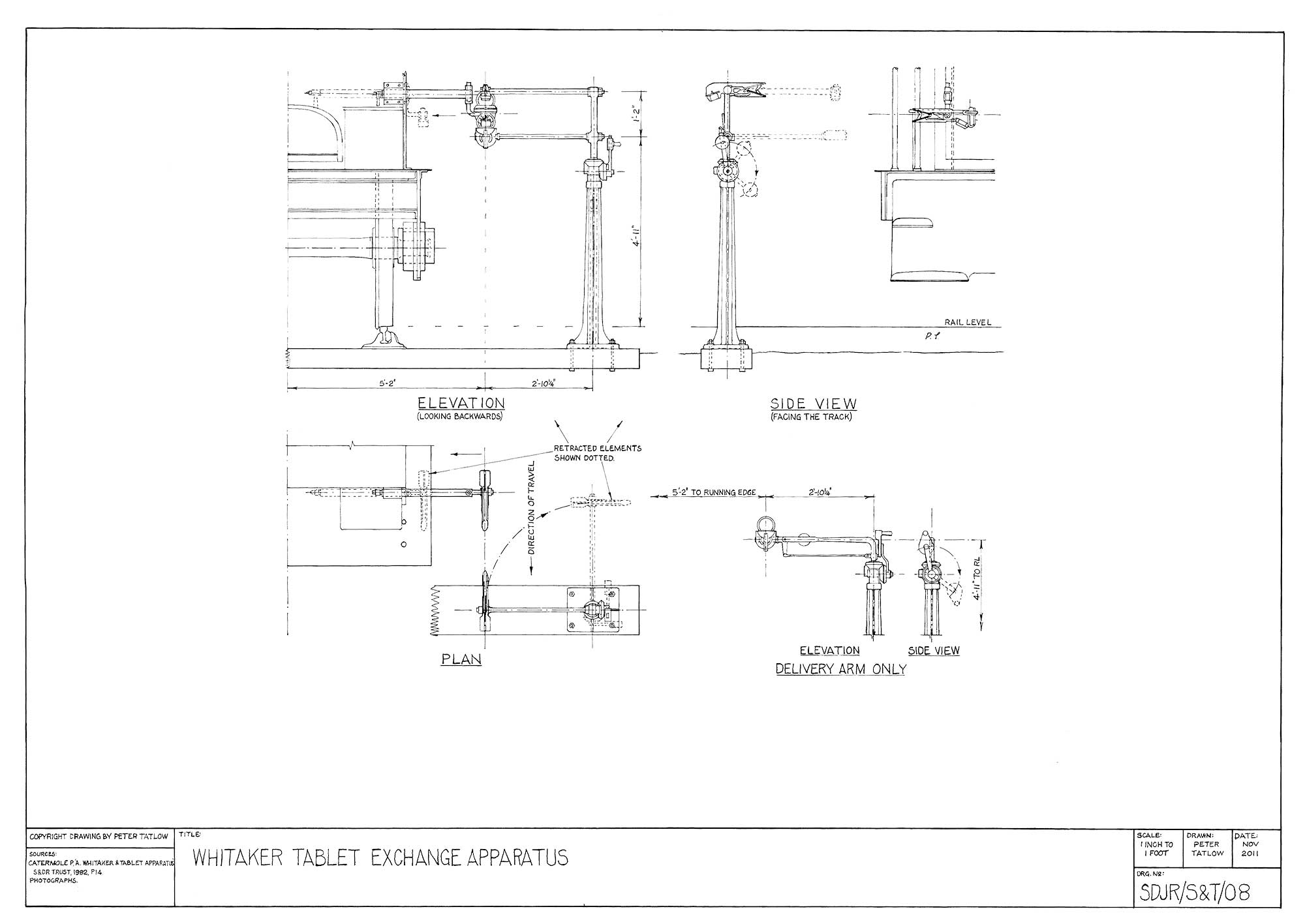
Figure 3/1 Whitaker tablet exchange apparatus. (Author)
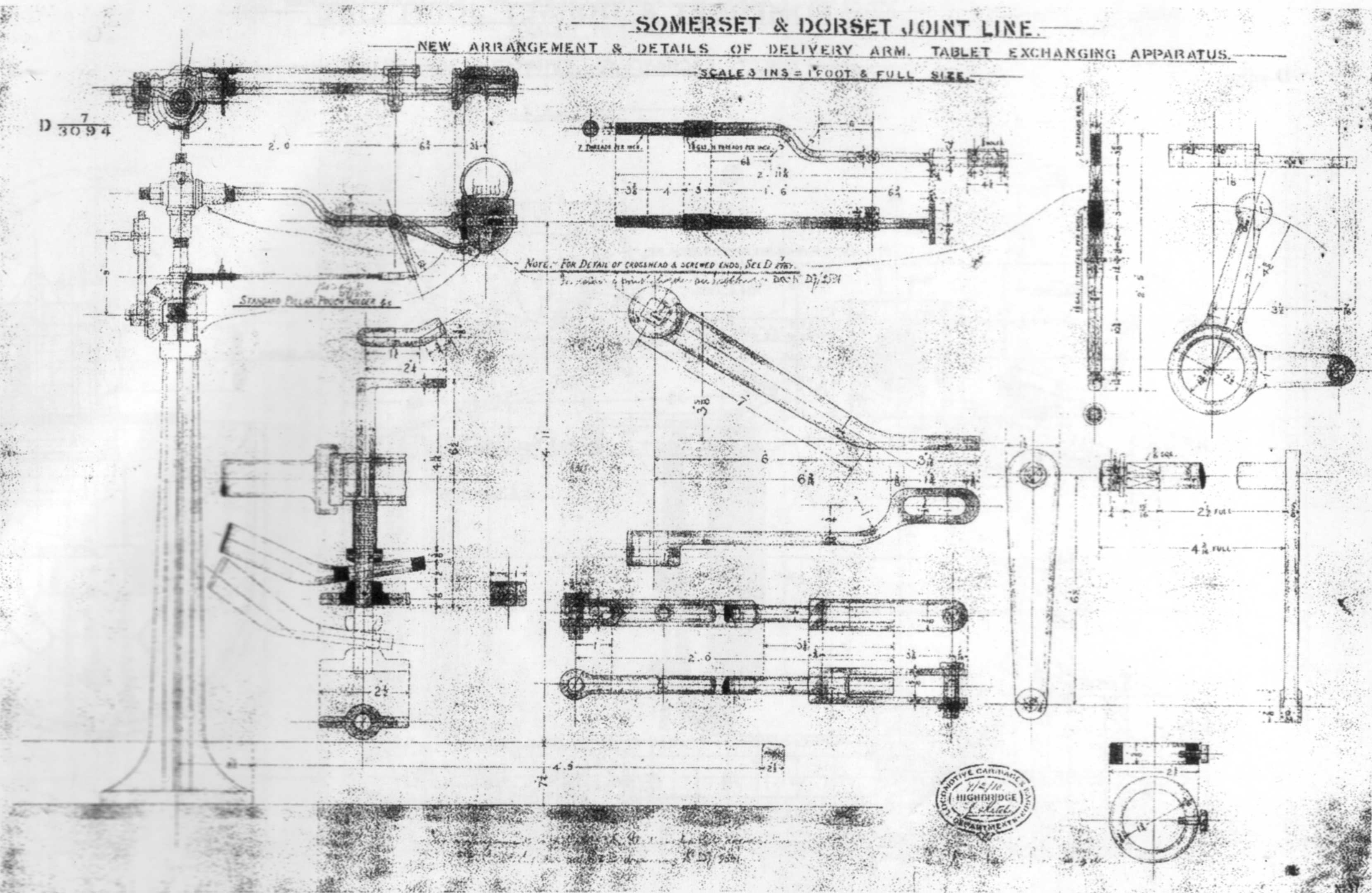
Figure 3/2 S&DJR new arrangement & details of delivery arm, Drg No. D7/3094.37, dated 7 Feb
1910. (S&DJR, courtesy Somerset & Dorset Railway Trust)
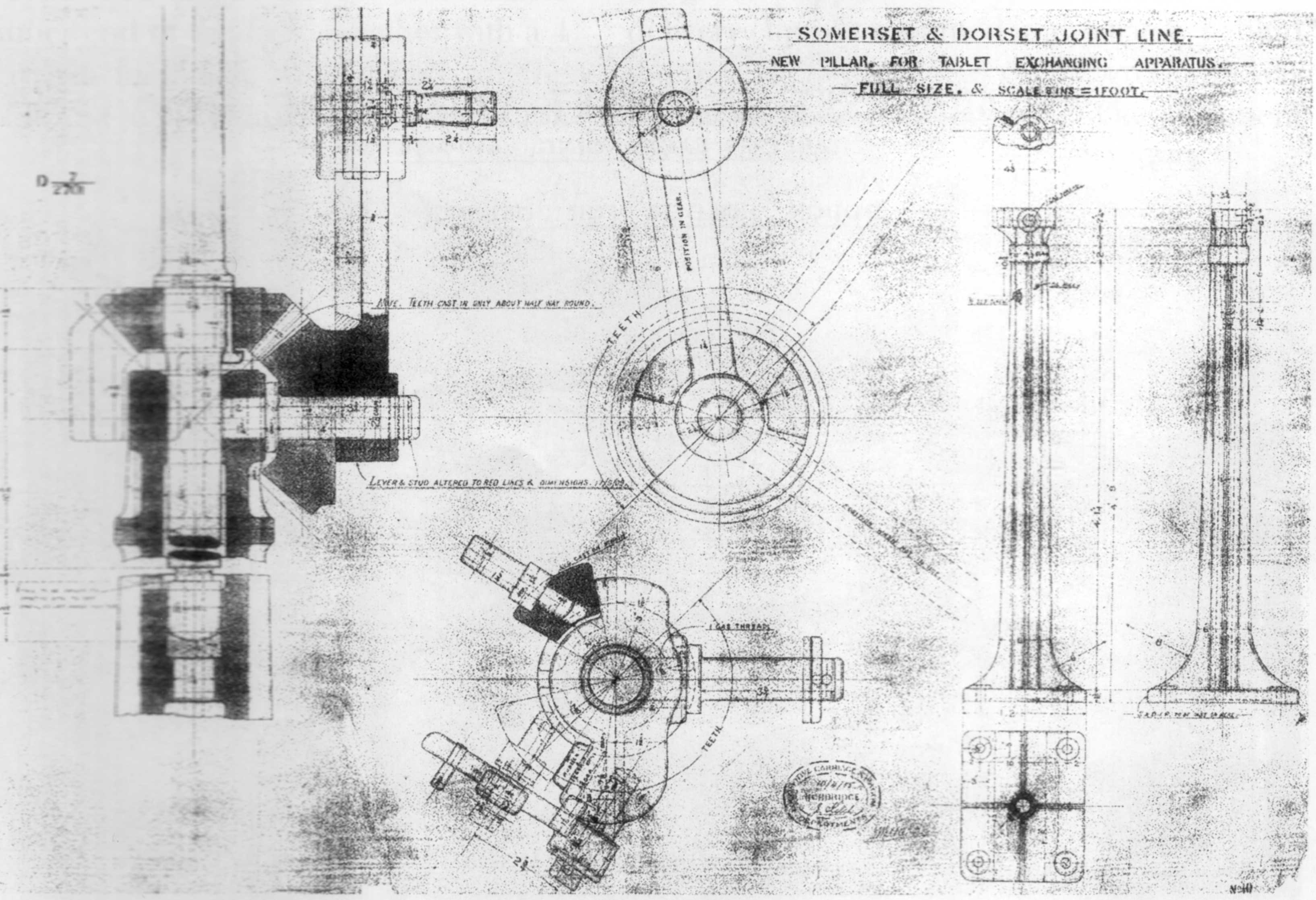
Figure 3/3 S&DJR new pillar, Drg No. D7/2701.10, dated 10 April 1905. (S&DJR, courtesy
Somerset & Dorset Railway Trust)
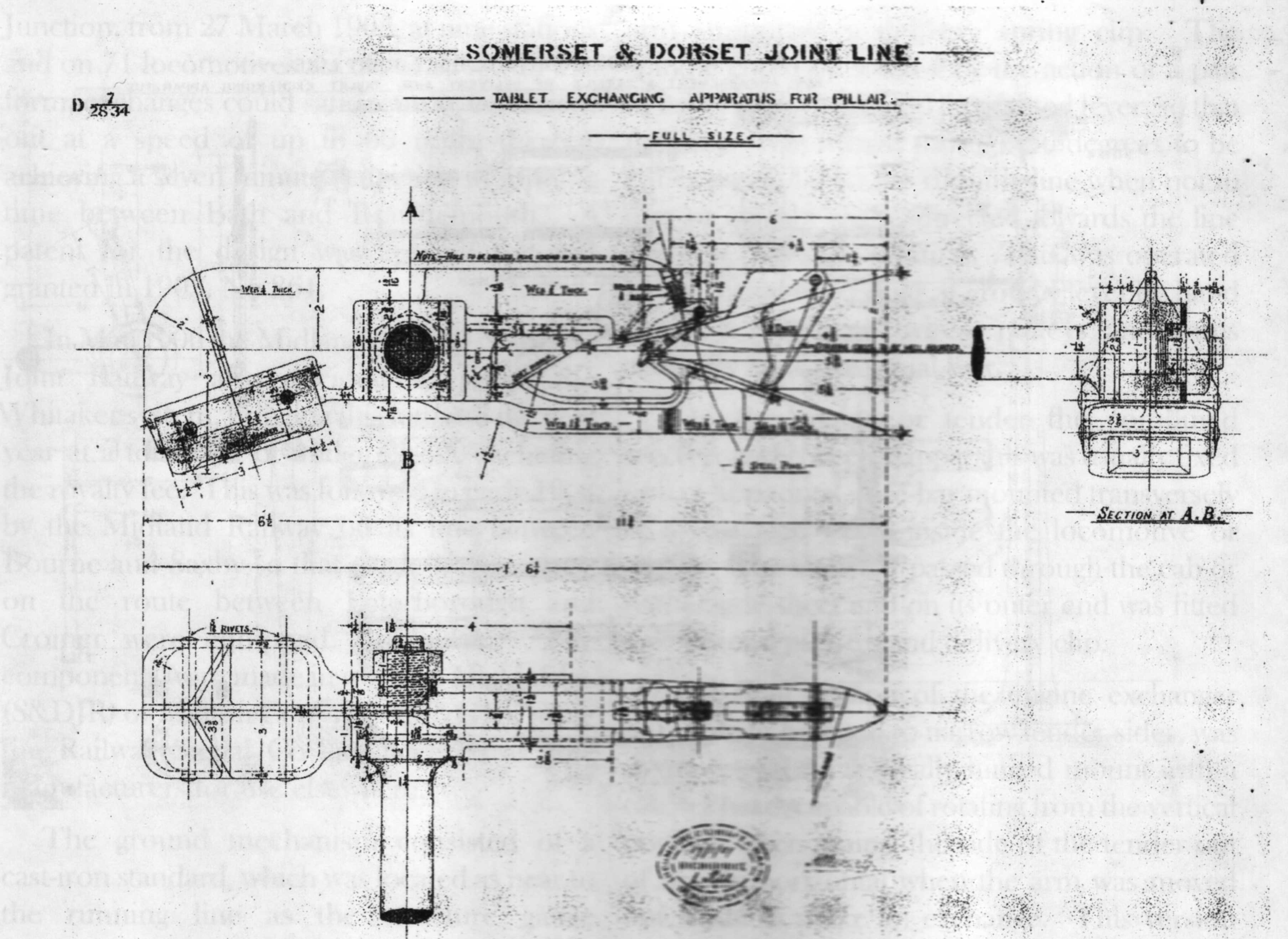
Figure 3/4 S&DJR tablet exchanging apparatus for pillar, Drg No. D7/2834.26, dated 17 Jan 1907.
(S&DJR, courtesy Somerset & Dorset Railway Trust)
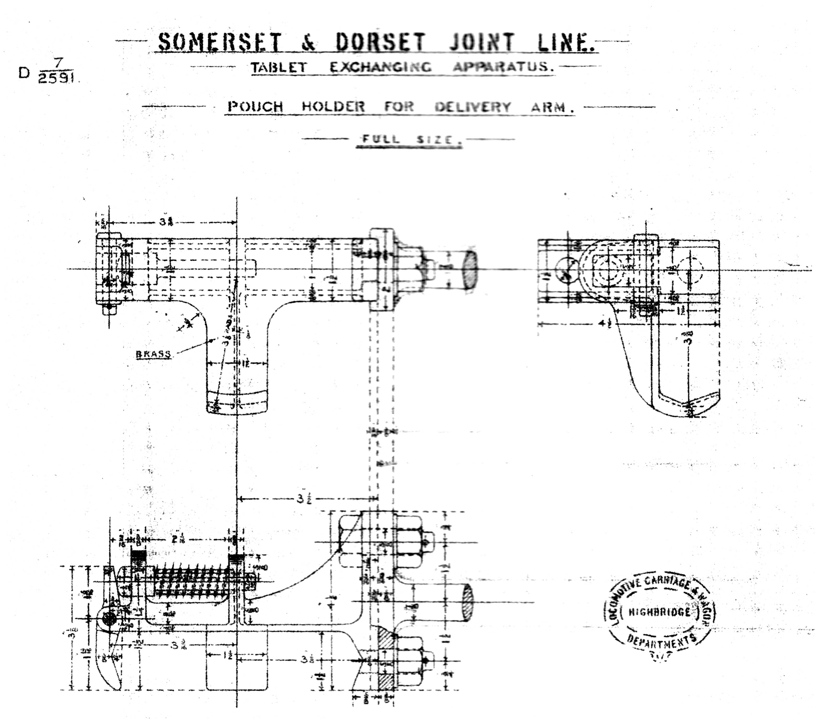
Figure 3/5 S&DJR tablet pouch holder, Drg No. D7/2591, noted in pencil 'for Bath –Midford section
only, but also listing size of the hole in the pouch for other sections. (S&DJR, courtesy Somerset &
Dorset Railway Trust)
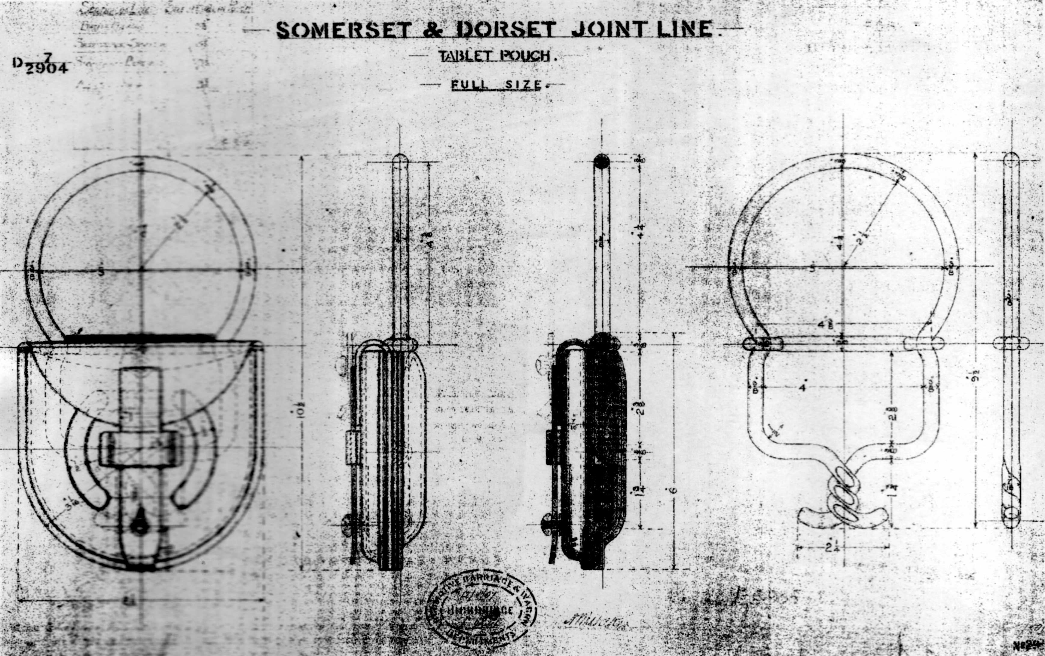
Figure 3/6 S&DJR tablet pouch, Drg No. D7/2904.29, dated 12 Aug 1907. (S&DJR, courtesy
Somerset & Dorset Railway Trust)
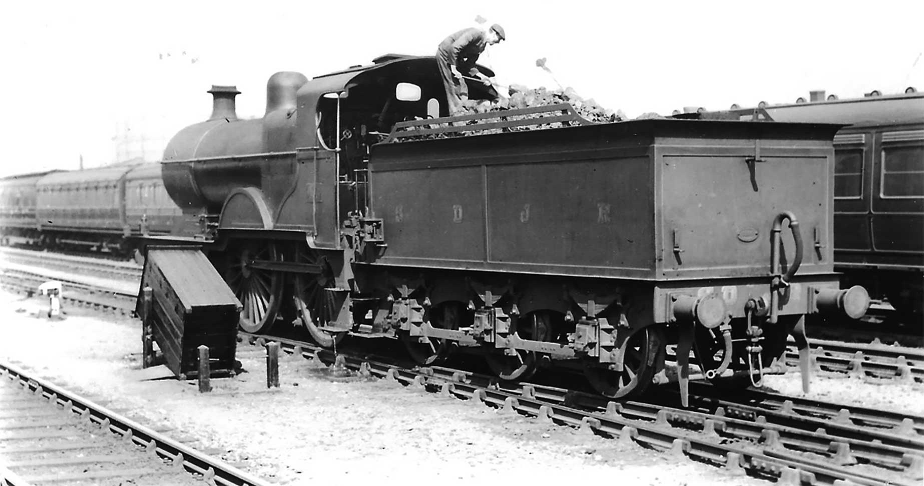
Plate 3/8 S&DJR 4-4-0 No. 42 at Bath on 21 May 1929 while the fireman trims the coal in the
tender. This is fitted with the alternative form of hinged mounting of the Whitaker apparatus on the left
hand side. (HC Casserley)
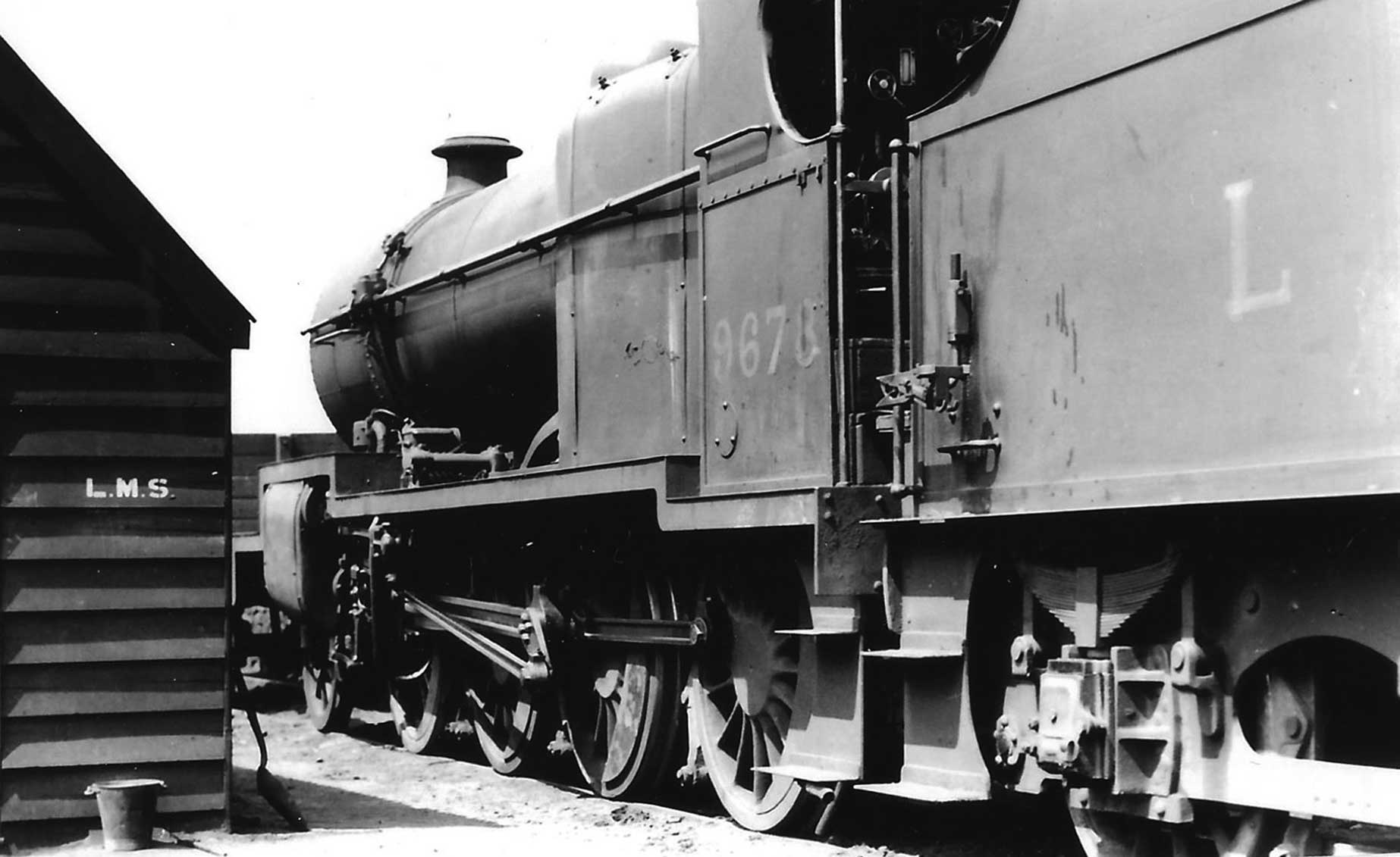
Plate 3/9 A closer view of the engine apparatus on ex-S&D 2-8-0 LMS No. 9678 at Bath on 9 June
1930. (HC Casserley)
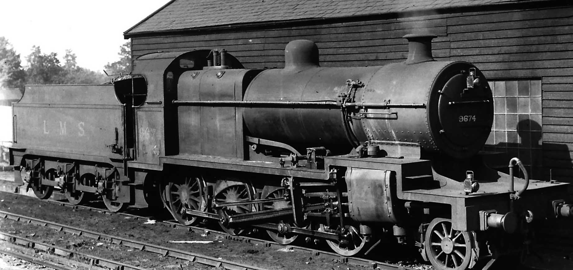
Plate 3/10 The right-hand side of sister engine LMS No. 9674 at Templecombe on 5 July 1930 equipped
with the apparatus on that side as well. (HC Casserley)
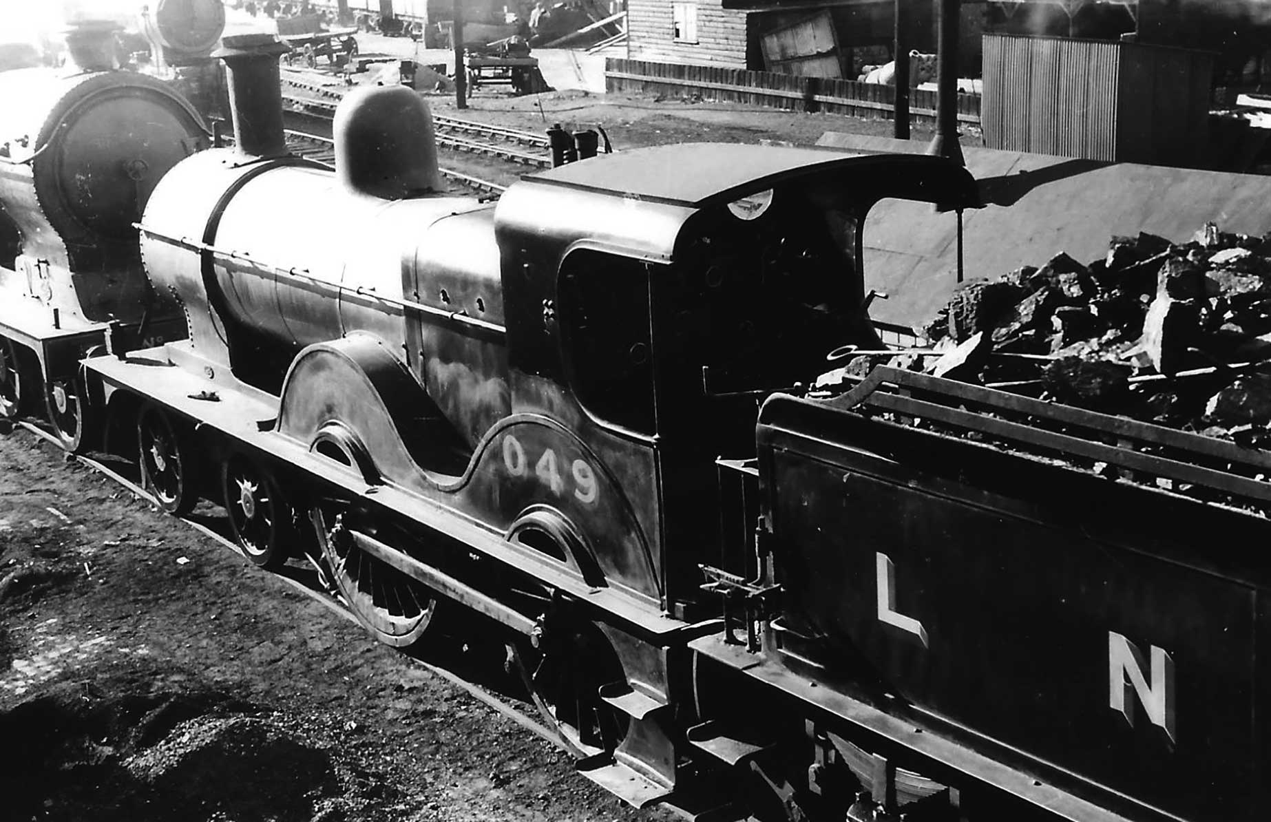
Peter 3/11 Looking down on M&GN 4-4-0 No. 049 at Peterborough East on 20 May 1938, after the LNER
had taken over the locomotive, stock showing the engine equipment on the left-hand side. (HC Casserley)
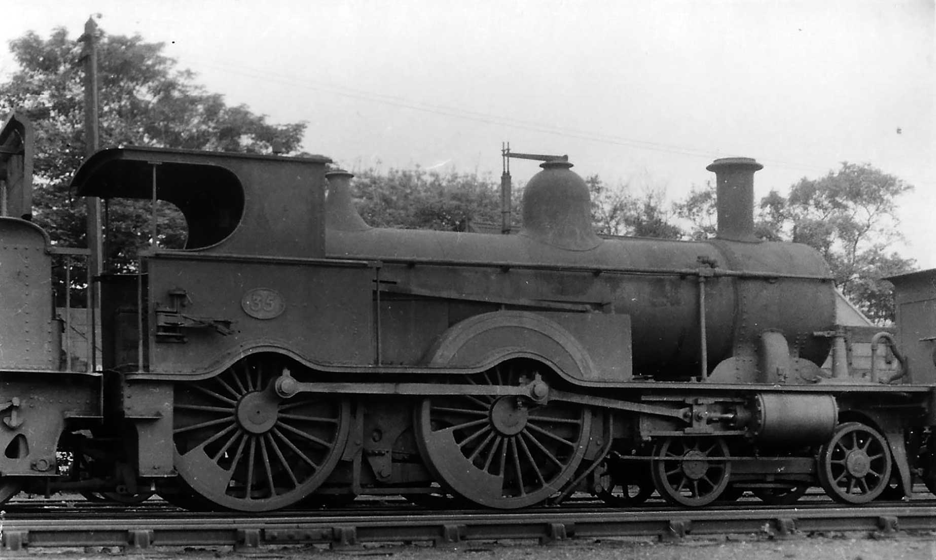
Plate 3/12 Like the S&DJR, the M&GN fitted the equipment of the right-hand side as well, as
demonstrated by this view of No. 35 at Melton Constable on 1 July 1936. (HC Casserley)
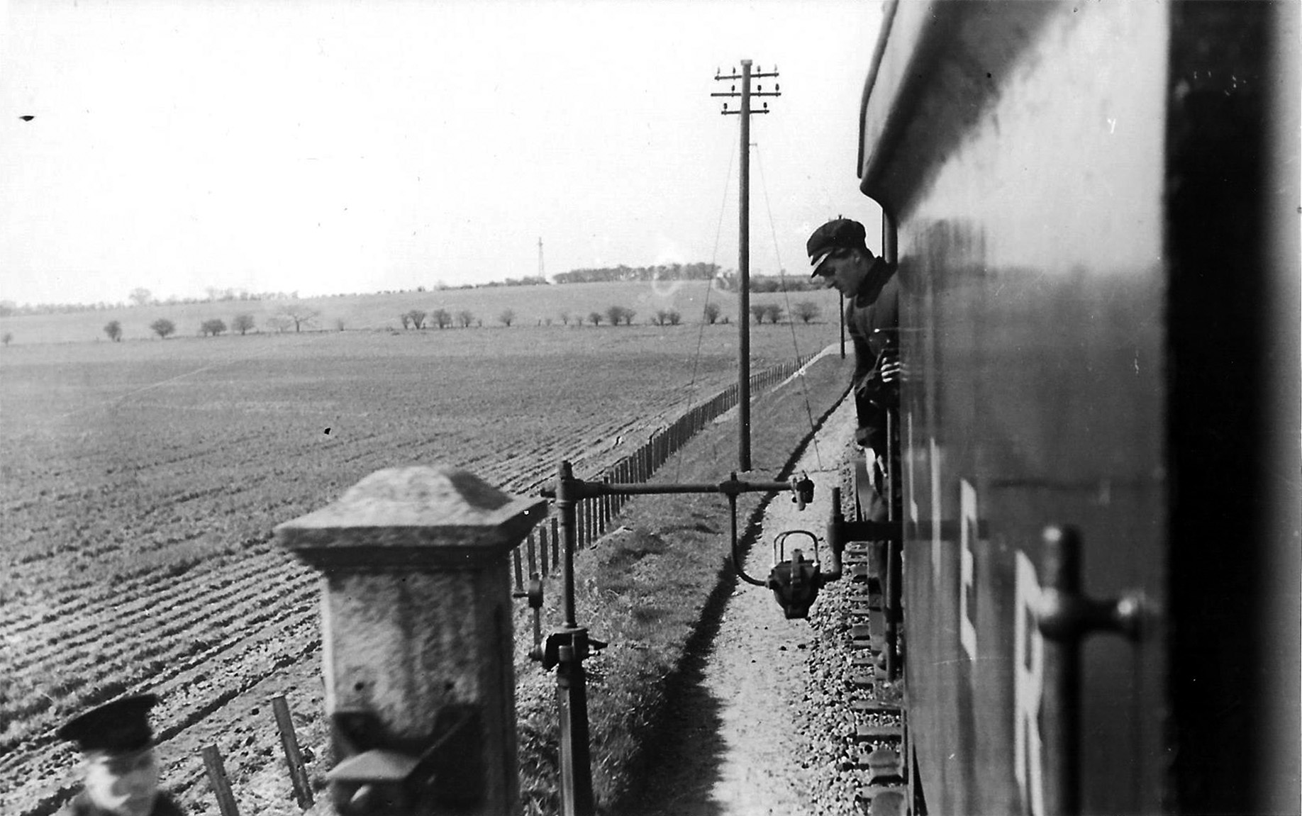
Plate 3/13 Our photographer, Henry Casserley was obviously interested enough to capture on film the
process of the exchange taking place, in this case leaving East Rudham on 16 April 1937. (HC
Casserley)
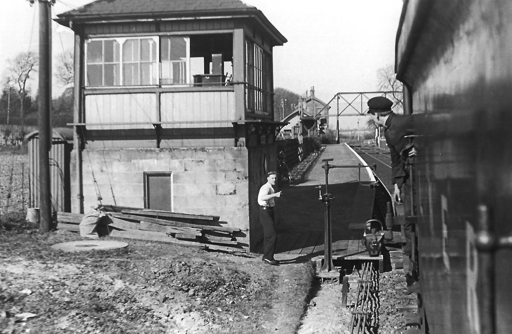
Plate 3/14 Again when approaching Massingham on the same day. The lineside equipment at both
locations cater for delivery and collection of the pouch containing the tablet in the final form of
apparatus with the delivering arm hung off the upper collector arm. (HC Casserley)
Site contents Copyright © LMS Society, 2024

April 19th, 2024
Site contents Copyright © LMS Society, 2024